6.1.1 Timer set up (standard configuration)
1. To be sure that the equipment is in the correct position we
recommend you put the provided template code 39599100 (3 - Figure
6-1) in the requested position, in this way identifying the requested
wall-mounting position. Considering the overall dimensions of the
equipment, put the top part of the template at 1450 mm from the
floor.
WARNING:
The installer will assess the consistency of the wall taking into
consideration the screw extraction load specified in paragraph 5.1.
2. Mark the mounting points and make the respective holes with a
diameter corresponding to the chosen screws.
Making reference to the template, use holes "A" for standard
installation. Use holes "B" for single stud installation.
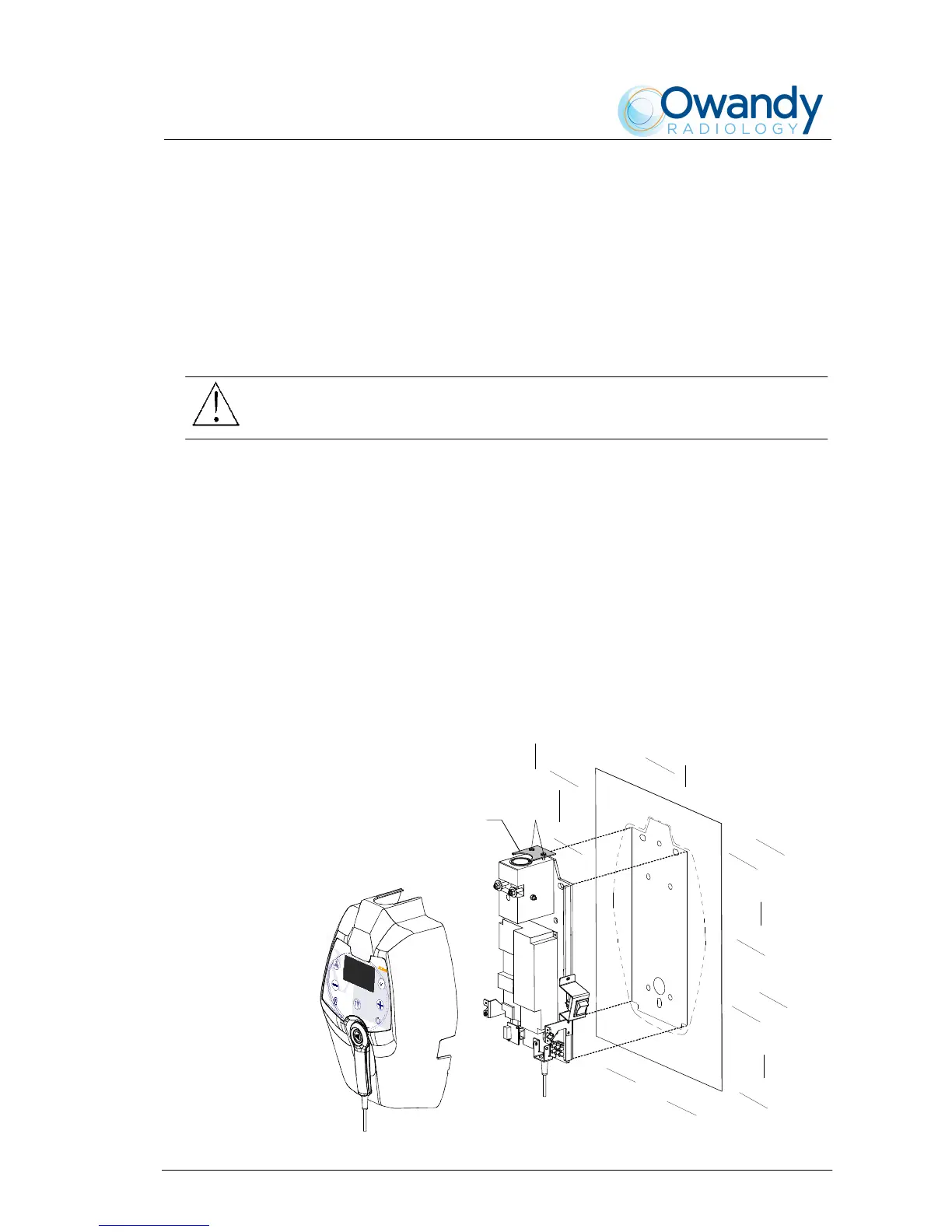
3. Remove the plastic timer cover (1 - Figure 6-1) loosening the two
sealing screws (2 - Figure 6-1) placed on the top part.
Do not remove completely the screws and the relevant plate (4 -
Figure 6-1); with the extention arm in place, will not be possible
to reassemble the plate.
To make the operation easier, disconnect all wires between wall plate
and cover.
4. Fix the timer to the wall using the relevant screws verifying the
perpendicularity of both axes with respect to the wall.
A
A
A
B
B
B
B
B
2
3
1
4
Figure 6-1