6.5.2 Electrical connection for Remote Timer version
6.5.2.1 Wall support connection
1. Remove the X-ray button complete of its support from the timer.
2. Connect the timer following the procedure listed in paragraph 6.5.1,
steps from 1 to 3.
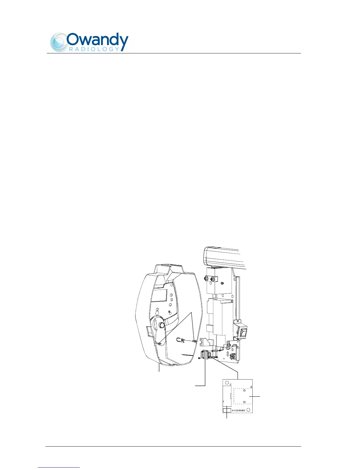
3. Assemble the Remote Interconnection Timer board (A8), included in
the Remote Timer box, on the timer as shown in Figure 6-20.
4. Connect the flat cable, supplied with the Remote Timer box, between
Driver board – connector X1 (Figure 6-19) – and A8 board – connector
X1 (Figure 6-20).
5. Connect the RJ 45 cable to the A8 board – connector X9 (Figure
6-20).
6. Assemble the two pins lock (1 - Figure 6-20) on the Remote Timer
cover (1 - Figure 6-18); these pins (code 2100511300) are included in
the mounting hardware packaging.
7. Place the cover on the timer taking care that the cover is positioned
under the upper plate (4 - Figure 6-1). Push the cover against the
locking pins and tighten the two upper screws (2 - Figure 6-1).
X1
X9
Remote Interconnection
Timer board (A8)
1
Figure 6-20