6.4.4.2 Remote Timer set up
1 To be sure that the equipment is in the correct position we
recommend you put the provided template code 39599101 (3 - Figure
6-18) in the requested position, in this way identifying the requested
wall-mounting position. Considering the overall dimensions of the
equipment, put the top part of the template at 1450 mm from the
floor.
2 Mark the mounting points and make the relevant holes with the
diameter corresponding to the chosen screws.
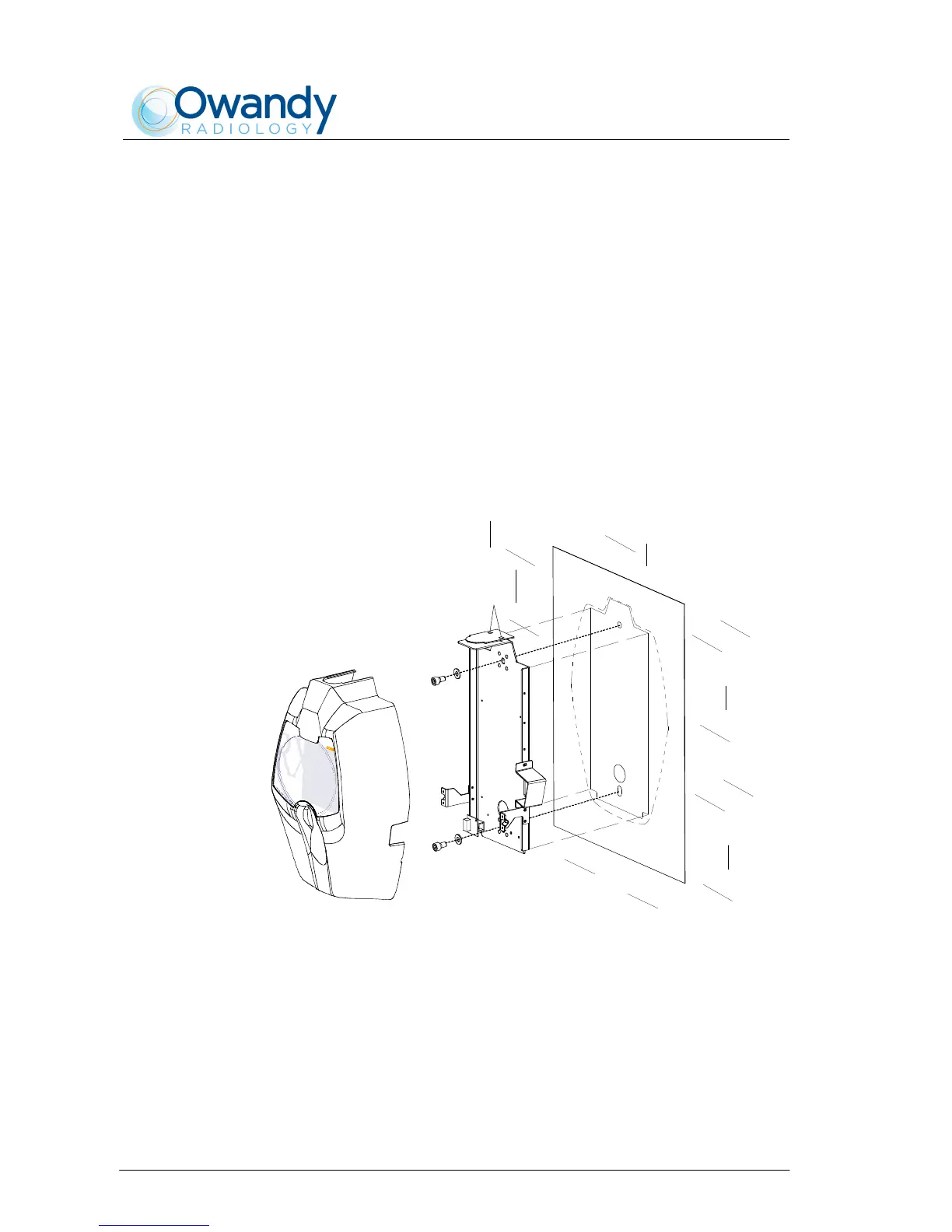
3 Remove the plastic timer cover (1 - Figure 6-18) by loosening the two
sealing screws (2 - Figure 6-18) placed on the top part.
4 Fix the timer to the wall using the provided screws (4 - Figure 6-18)
verifying its perpendicularity with the wall accordingly to both axis.
2
3
1
4
4
Figure 6-18