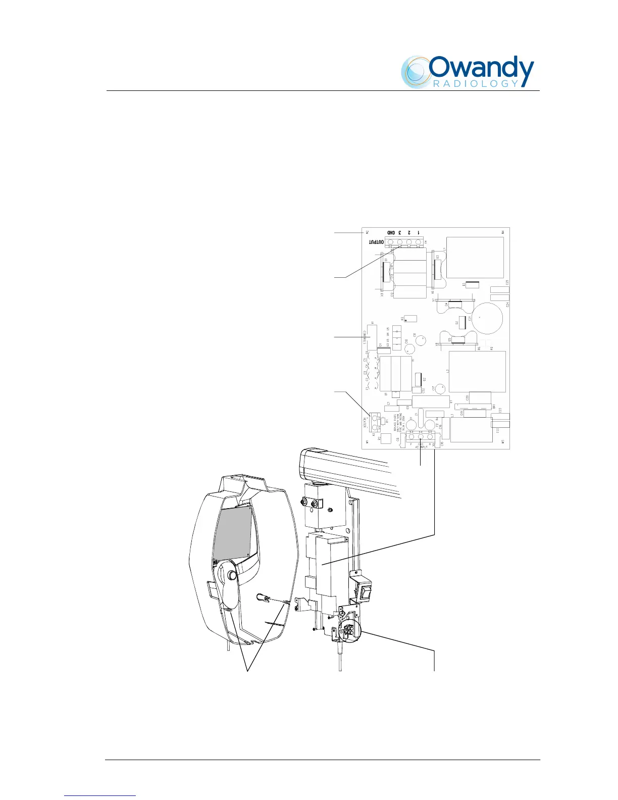
5. Connect the cables between timer and cover: flat cable between CPU
board – connector X1 – and Driver board – connector X1
(CONTROLS); X-ray button cable to CPU board – connector X6.
6. Place the cover on the timer taking care that the cover is positioned
under the upper plate (4 – Figure 6-1). Push the cover against the
locking pins and tighten the two upper screws (2 – Figure 6-1).
X4
W2
X2
Main power supply
terminal strip
1
X1
X5
Figure 6-19