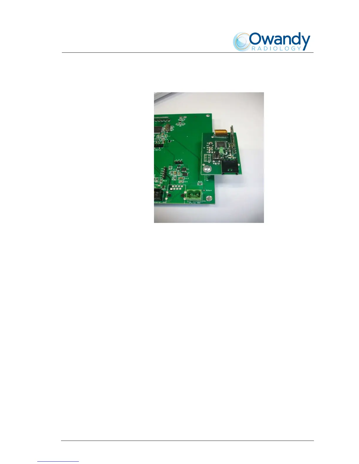
4. Assemble the A6 Radio board on the CPU board using the provided
screw (Figure 6-17).
Figure 6-17
5. Reassemble the CPU board on the timer cover.
6. Connect the X7 cable between CPU board – connector X7 -
and Radio board – connector J7.
7. Reconnect the cables between timer and CPU board and
reassemble the plastic timer cover.