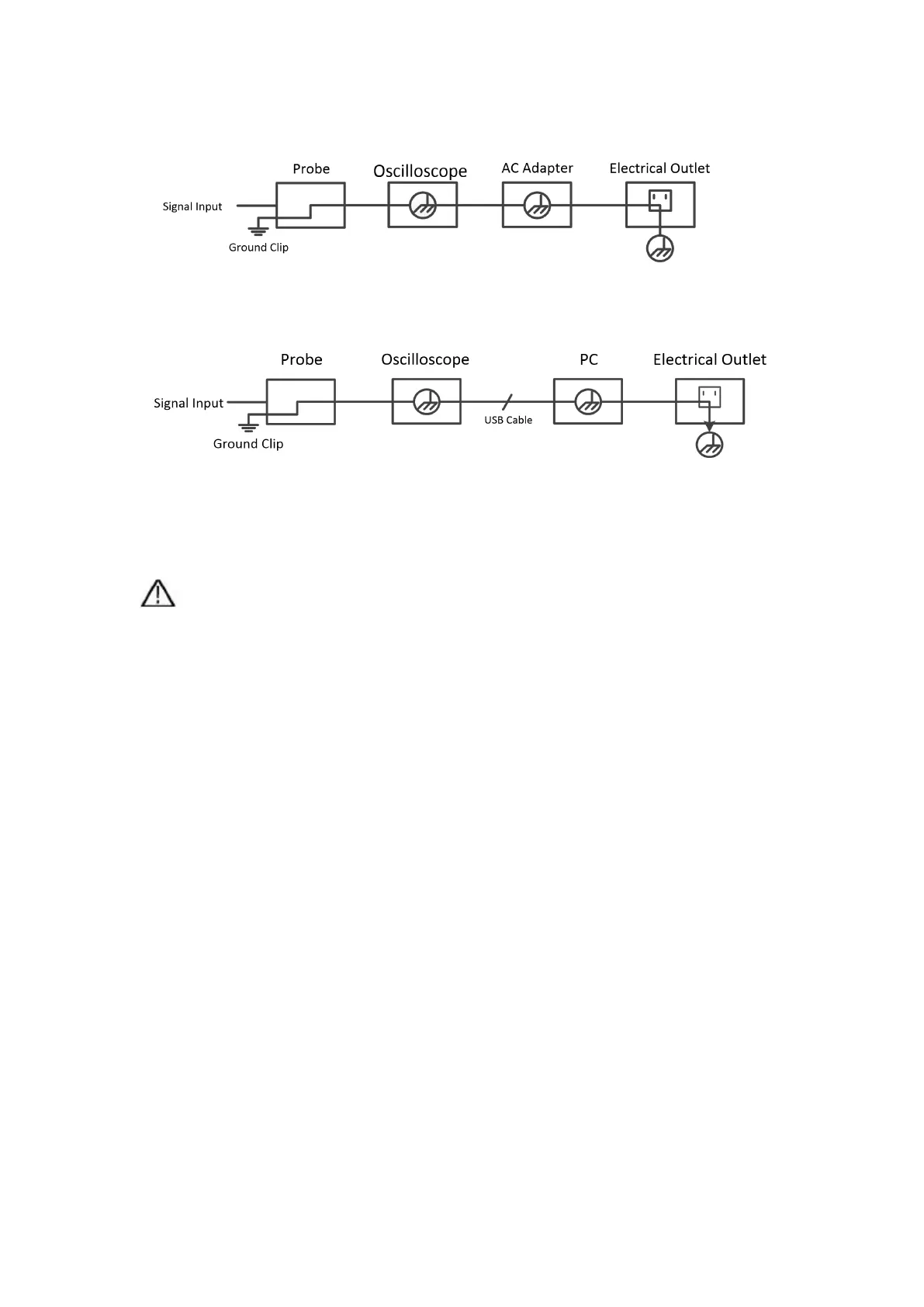
Schematic diagram of the internal ground wire connection of the oscilloscope:
Schematic diagram of internal ground connection when oscilloscope is
connected with computer through the port:
When the oscilloscope is AC powered by adapter or connected with AC
powered computer through the port, it is not allowed to measure the primary
power supply of power grid.
Warning:
If the input port of the oscilloscope is connected to a voltage with a peak value
higher than 42V (30vrms) or a circuit with a peak value of more than 4800 VA,
the following measures shall be taken to avoid electric shock or fire:
Only voltage probes, test wires and adapters with proper insulation
attached to the oscilloscope or accessories suitable for oscilloscope
instrument series products specified by our company shall be used.
Before use, check the multimeter test probe, oscilloscope probe and
accessories for mechanical damage. If damage available, replace it.
Remove all unused multimeter test probes, oscilloscope probes and
accessories (power adapter, USB, etc.).
Firstly, plug the power adapter into the AC socket, and then connect it to
the oscilloscope.
When testing in a CAT II environment, do not connect a voltage higher
than 400 V to any input port.
When testing in a CAT II environment, do not connect a voltage with a
voltage difference of more than 400 V to the isolated input port.