4 Installation
(1)
(2)
(5)
(4)
(3)
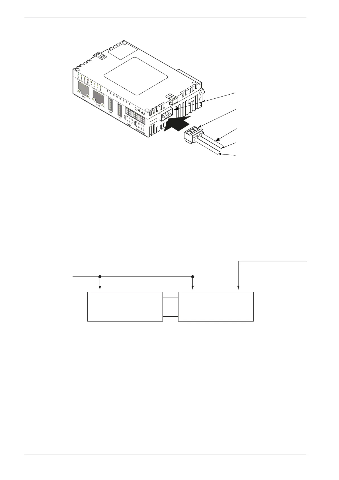
(1)
Power supply connector
(2)
Power supply cable (AFPG805)
(3)
Brown: 24V DC
(4)
Blue: 0V
(5)
Green: must be connected to framing ground
The FP-I4C unit will turn ON as soon as the power supply has been connected.
When connecting the power supply (class 2 circuit) make sure the polarity (+/-) is correct.
The FP-I4C unit and the PLC have to be supplied by THE SAME power supply unit. If power
is supplied, the green POWER LED will be ON after self-test.
FP-I4C
Ethernet
CPU
(1)
(1)
Power supply
Please read the Recommendations for installation (page 17).
Please also read the "FP-I4C Installation Instructions Leaflet" supplied with your FP-I4C.
28 FP-I4C