5 Wiring
(1)
(2)
(3)
(4)(5)
R (COM1)
G (COM1)
S/ - (COM2)
F1
S (COM1)
G (COM1)
S/ - (COM2)
S/ - (COM2)
F2
R/ + (COM2)
R/ + (COM2)
E
SGSG
(1) Brown: SG to pin1
(2) Red, white: R+ to pin2
(3) Orange, green: - (COM2) to pin 3
(4) PLC TOOL port mini-DIN, 5-pin male
(5) FP-I4C 16-pin connector
5.2 Connecting the PLC COM
FP0R, FPS, FP-X, FP0H, FP7: Use either COM1 or COM2 for communication (depending on
the PLC interface settings)
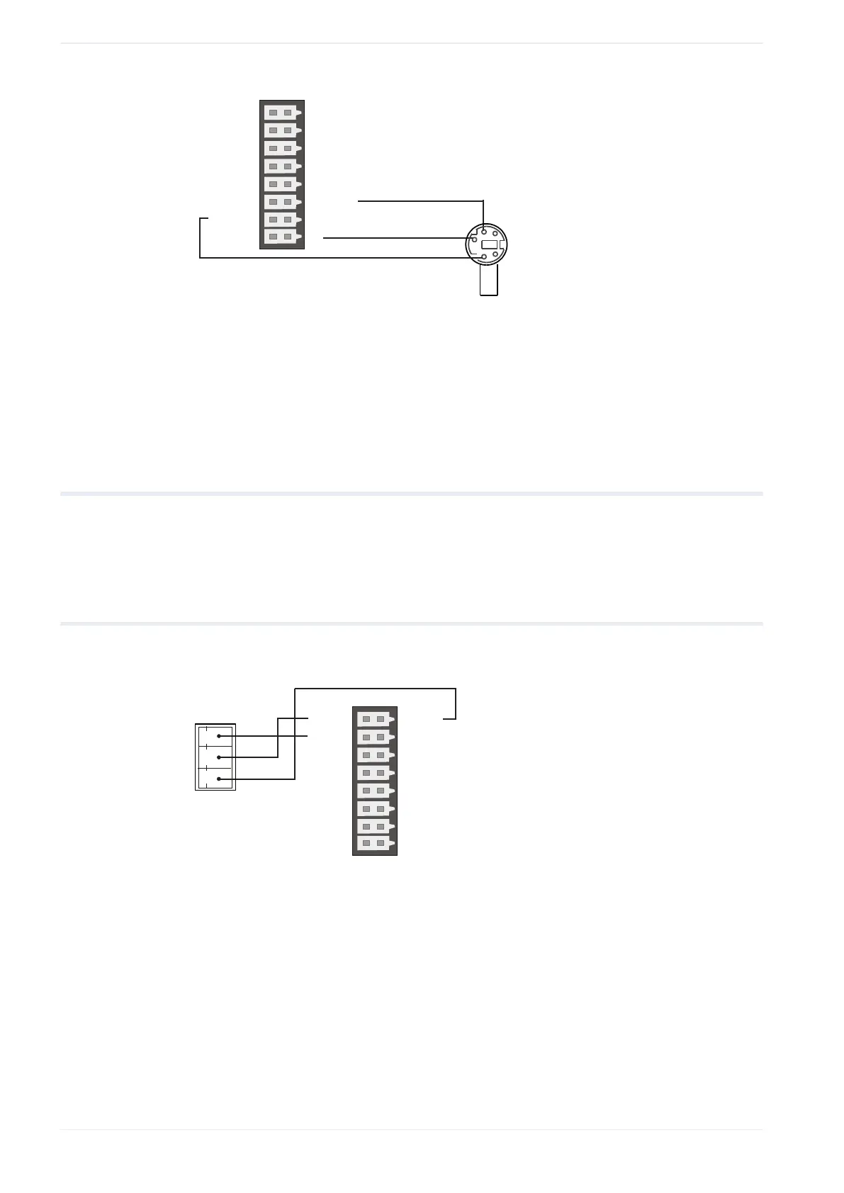
5.2.1 Using the PLC COM port with the FP-I4C COM1
Wire the PLC COM port with the FP-I4C 16-pin connector (COM1)
(1)
(3)
(4)
(5)
(2)
R (COM1)
G (COM1)
S/ - (COM2)
F1
S (COM1)
G (COM1)
S/ - (COM2)
S/ - (COM2)
F2
R/ + (COM2)
R/ + (COM2)
E
SGSG
S R G
(1) G: G (COM1) for system ground
(2) R: S (COM1) for receive data from FP-I4C
(3) S: R (COM1) for send data to FP-I4C
(4) PLC COM port, 3-pin screw terminal
(5) FP-I4C 16-pin connector
30 FP-I4C