Note
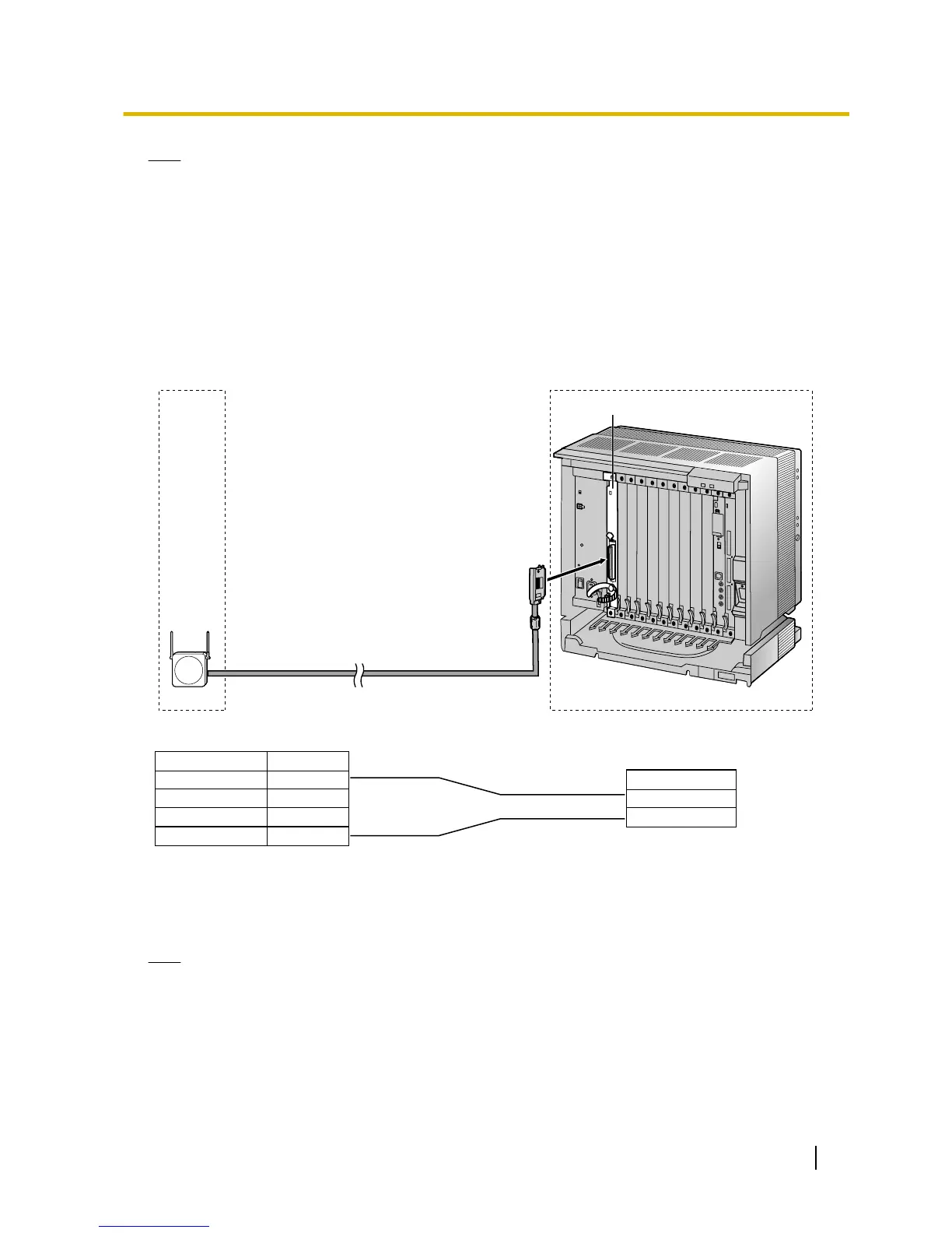
• The no. 4 and no. 5 pins (Master) of the CS must be connected to a pair of pins on the DHLC/DLC
card. Then
use 4 consecutive pairs of pins on the DHLC/DLC card, starting with the pins corresponding
to the Master, as in the example above.
• When connecting multiple KX-TDA0158CE CSs to a DHLC/DLC card, make sure that the no. 4 and
no. 5 pins (Master) of adjacent CSs are at least 3 pairs of pins away on the card.
• CS connections must be made within the same DHLC/DLC card.
• When a wrong connection is made, satisfactory performance of the CS cannot be guaranteed. Check
the connection of CS and the PBX using the Maintenance Console. For information about how to view
CS information using the Maintenance Console, refer to "2.6.14 Utility—CS Information" in the PC
Programming Manual.
KX-TDA0141CE
Accessories and User-supplied Items for the CS
Accessories (included): Screws ´ 2, Washers ´ 2
User-supplied (not included): RJ11 connector
Note
For details about
DHLC card or DLC card, refer to "2.7.2 DHLC8 Card (KX-TDA0170)", "2.7.3 DLC8 Card
(KX-TDA0171)", or "2.7.4 DLC16 Card (KX-TDA0172)".
Installation Manual 223
2.10.7 Connecting a Cell Station to the PBX
 Loading...