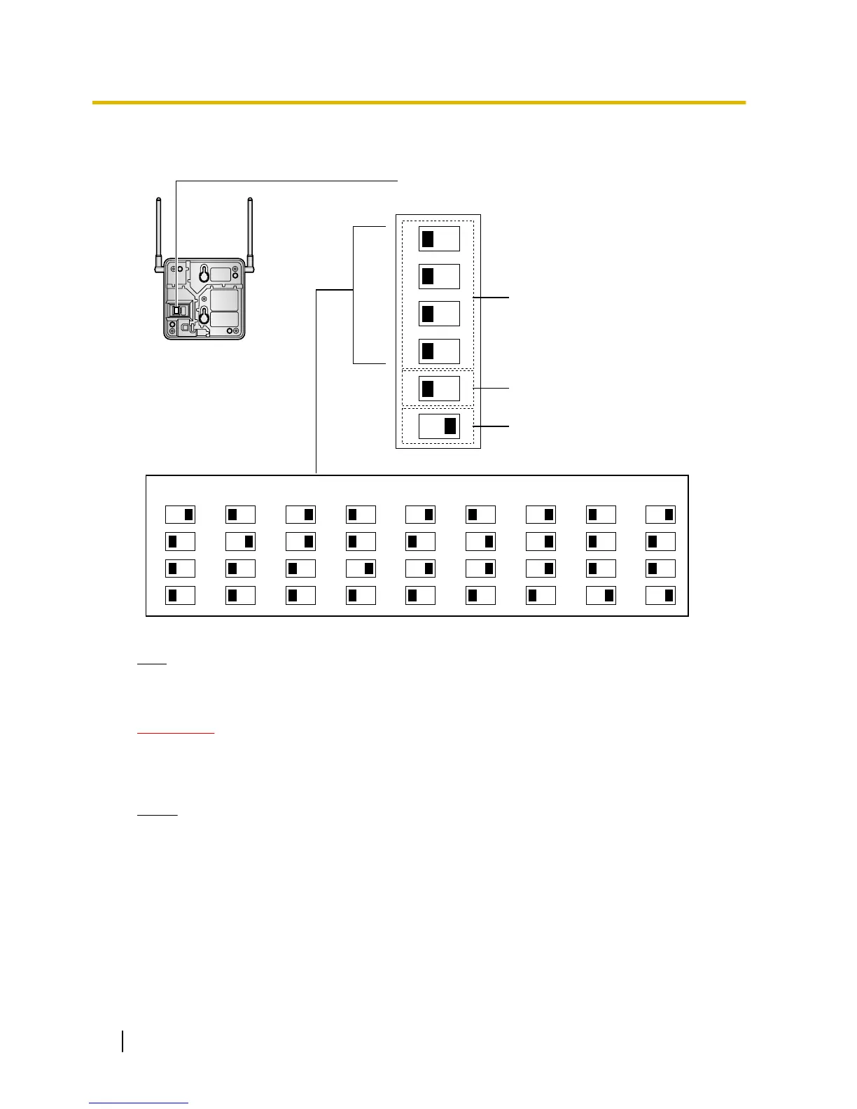
CS Number Switch
CS no. 1 CS no. 2 CS no. 3 CS no. 4 CS no. 5 CS no. 6 CS no. 7 CS no. 8 CS no. 9
1
2
3
4
1
2
3
4
1
2
3
4
1
2
3
4
1
2
3
4
1
2
3
4
1
2
3
4
1
2
3
4
1
2
3
4
DIP Switch
1
2
3
4
5
6
OFF ON
Radio Signal
Test Switch
Keep this switch at the default
"OFF" position. Otherwise, the
CS will not function.
Note
If more than 1 CS is in Radio Signal Test mode, each CS must have a unique CS number.
4. After setting the
DIP switches, connect the CS to an AC adaptor/battery box using a power supply adaptor.
WARNING
The AC adaptor
should be connected to a vertically oriented or floor-mounted AC outlet. Do not
connect the AC adaptor to a ceiling-mounted AC outlet, as the weight of the adaptor may cause
it to become disconnected.
Notice
If
the
Power
Supply Select switch is set to ON in step 3, connect the CS to an AC adaptor/battery box.
If it is set to OFF, connect the CS to a CSIF/DLC/DHLC card (KX-TDA0151/KX-TDA0152 only).
244 Installation Manual
2.11.4 Before Site Survey
 Loading...