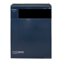
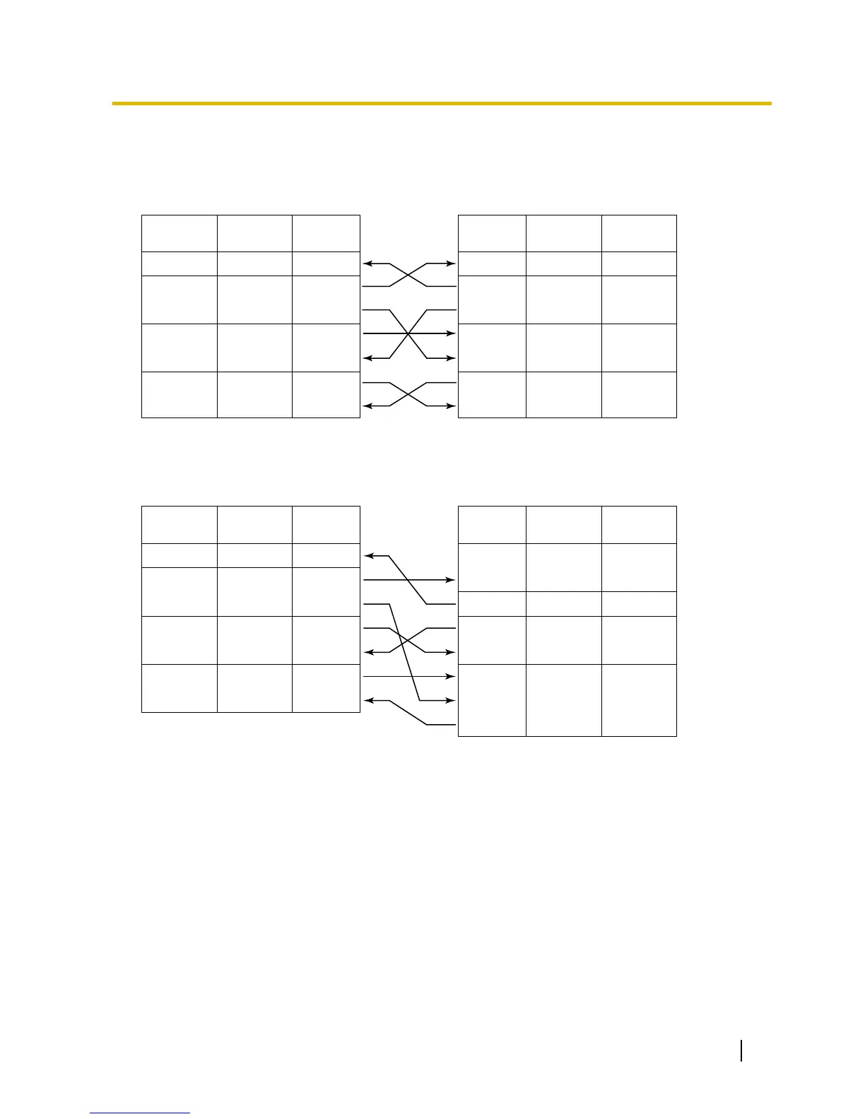
EasyManua.ls Logo

Panasonic KX-TDA600

Panasonic KX-TDA600
338 pages
To Next Page IconTo Next Page
To Previous Page IconTo Previous Page
Loading...
Connection Charts
For connecting a printer/PC with a 9-pin RS-232C connector
PBX (9-pin) Printer/PC (9-pin)
Circuit Type
(EIA)
Signal
Name
Pin No. Pin No.
Signal
Name
Circuit Type
(EIA)
BB RD (RXD) 2
BA SD (TXD) 3
CD ER (DTR) 4
AB SG 5
CC DR (DSR) 6
CA RS (RTS) 7
CB CS (CTS) 8
2 RD (RXD) BB
3 SD (TXD) BA
4 ER (DTR) CD
5SG AB
6 DR (DSR) CC
7 RS (RTS) CA
8 CS (CTS) CB
For connecting a printer/PC with a 25-pin RS-232C connector
PBX (9-pin) Printer/PC (25-pin)
Circuit Type
(EIA)
Signal
Name
Pin No.
Signal
Name
Circuit Type
(EIA)
BB RD (RXD) 2
BA SD (TXD) 3
CD ER (DTR) 4
AB
SG 5
CC
DR (DSR) 6
CA RS (RTS) 7
CB
CS (CTS) 8
1FG AA
3 RD (RXD) BB
2 SD (TXD) BA
20
ER (DTR) CD
7
SG AB
5 CS (CTS) CB
6
DR (DSR) CC
CF
4 RS (RTS)
Pin No.
RS-232C Signals
Receive Data (RXD):…(input)
Conveys signals from the printer or the PC.
Transmit Data (TXD):…(output)
Conveys signals from the unit to the printer or the PC. A "Mark" condition is held unless data or BREAK
signals are being transmitted.
Data Terminal Ready (DTR):…(output)
This
signal line
is turned ON by the unit to indicate that it is ON LINE. Circuit ER (DTR) ON does not indicate
that communication has been established with the printer or the PC. It is switched OFF when the unit is
OFF LINE.
Signal Ground (SG)
Connects to the DC ground of the unit for all interface signals.
Data Set Ready (DSR):…(input)
Installation Manual 297
2.14.1 Connection of Peripherals

Table of Contents

Other manuals for Panasonic KX-TDA600

Related product manuals