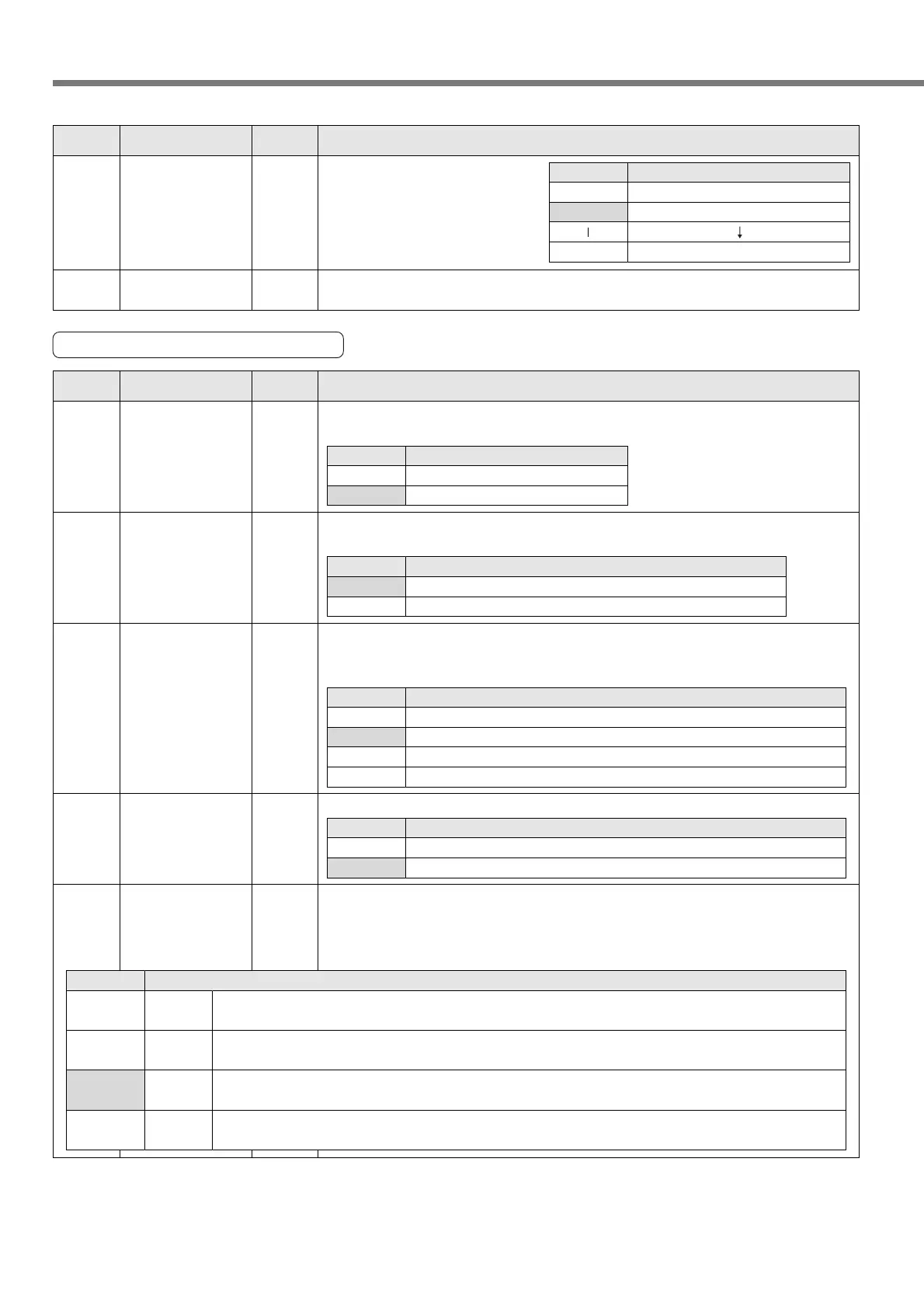
66
Parameter Setup
4D
*
0 to 31
<0>
FIR filter set up You can set up the moving average times of the FIR filter covering the internal
command pulse. (Setup value + 1) become average travel times.
4C 0 to 7
<1>
Smoothing filter You can set the time constant of
the primary delay firter covering
the internal command pulse in 8
steps.
Setup value
0
<1>
7
Time constant
No filter function
Time constant small
Time constant large
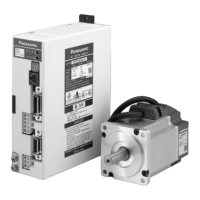
Servo
PrNo.
Setup
range
Title Function/Content
Standard default : < >
Parameters for Input Signals
53 0 to 1
<1>
Over-travel inhibit
input valid
Specify whether to enable or disable the CW/CCW over-travel inhibit input (CWL:
CN X5 Pin 20, CCWL: CN X5 Pin 19).
Setup value
0
<1>
Description
Disable
Enable
54 0 to 1
<0>
Over-travel inhibit
input logic
Set the logic of the CW/CCW over-travel inhibit input (CWL: CN X5 Pin 20, CCWL:
CN X5 Pin 19).
Setup value
<0>
1
Description
Over-travel is inhibited by opening the connection to COM–.
Over-travel is inhibited by closing the connection to COM–.
56 0 to 1
<1>
Home sensor
input logic
Set the logic of the Home sensor input (Z-LS: CN X5 Pin 21).
Setup value
0
<1>
Description
Home sensor input is enabled by opening the connection to COM–.
Home sensor input is enabled by closing the connection to COM–.
55 0 to3
<1>
Over-travel inhibit
input operation
setting
Select an operation when the CW/CCW over-travel inhibit input (CWL: CN X5 Pin
20, CCWL: CN X5 Pin 19) has been made. An operation is not tripped before
homing has completed, even if “0” or “1” is selected.
Setup value
0
<1>
2
3
Description
An operation decelerates, stops and trips after the stop.
An operation stops in deceleration time “0” and trips after the stop.
An operation decelerates and stops, but it does not trip after the stop.
An operation stops in deceleration time “0”, but it does not trip after the stop.
57
*
0 to 3
<2>
Selecting
the number of
input points
Select the number of point specifying inputs (P1IN to P32IN: CN X5 Pin 3, 4, 5, 6, 7
and 8). The number of present position outputs (P1OUT to P32OUT: CN X5 Pin 29,
30, 31, 32, 33 and 34) also becomes the same as that of selected point specifying
input.
Setup value
Description
P1IN to P4IN: CN X5 Pin 3, 4 and 5, and P1OUT to P4OUT: CN X5 Pin 29, 30 and 31 only are enabled.
The number of positioning points is 4 and a maximum number of points is 7.
P1IN to P8IN: CN X5 Pin 3, 4, 5 and 6, and P1OUT to P8OUT: CN X5 Pin 29, 30, 31 and 32 only are enabled.
The number of positioning points is 12 and a maximum number of points is 15.
P1IN to P16IN: CN X5 Pin 3, 4, 5, 6 and 7, and P1OUT to P16OUT: CN X5 Pin 29, 30, 31, 32 and 33 only are enabled.
The number of positioning points is 28 and a maximum number of points is 31.
P1IN to P32IN: CN X5 Pin 3, 4, 5, 6, 7 and 8, and P1OUT to P32OUT: CN X5 Pin 29, 30, 31, 32, 33 and 34 only are enabled.
The number of positioning points is 60 and a maximum number of points is 63.
3 bits
4 bits
5 bits
6 bits
0
1
<2>
3
Servo
PrNo.
Setup
range
Title Function/Content
Standard default : < >
<Notes>
• For servo parameters which No. have a suffix of "*", changed contents will be validated when you turn on
the control power.