48
Setup with the Front Panel
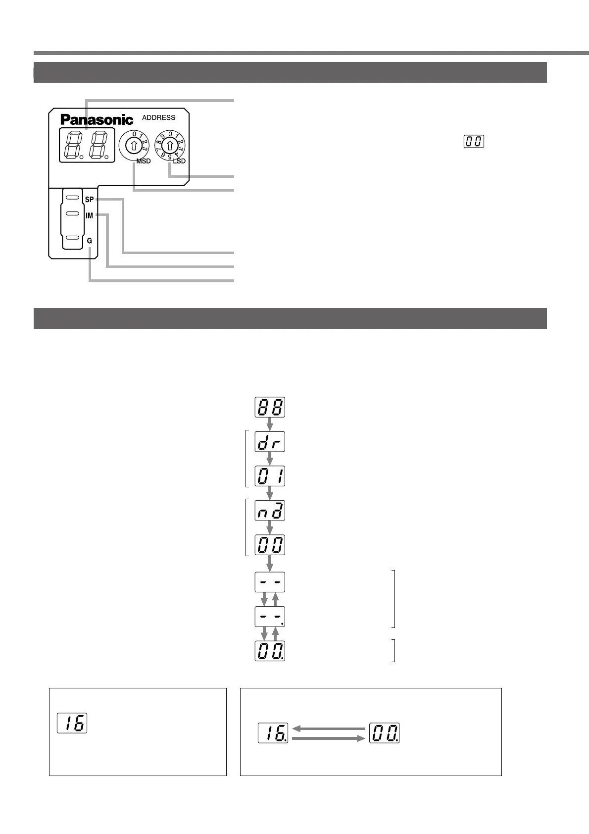
Composition of Touch Panel and Display
Display LED (2 digits)
In the case of an error, the alarm code will flash.
In the case of a warning, the warning code (about 2 seconds)
will alternate at about 4 seconds intervals with .
ID address setup rotary switch
LSD : Lower-shifting (Default : 0)
MSD : Upper-shifting (Default : 0)
For manufacturers' use only.
(Not for individual use)
Output signal (Analog signal)
Speed monitor output
Torque monitor output
Signal ground
Initial Status of the Front Panel Display (7-Segment LED)
When an alarm has been given, an alarm code of two-digit decimal number blinks on the front panel display
(7-segment LED) of this servo driver. When no alarm is given, the display shows as follows:
After approximately 2 seconds
All the segments turn on
(Light check)
Baud Rate indicated
ID address indicated
Hyphens indicated
An alarm code blinks.
(In the case of overflow)
• When an alarm has been given
A dot blinks
(at the right-hand side)
Normal display
(Alarm code 0)
After approximately 0.5 seconds
(A set value)
(A set value)
Control power supply
turns on
After approximately 0.5 seconds
After approximately 0.5 seconds
After approximately 0.5 seconds
Main power supply
turns off
SERVO READY = 0
Main power supply
turns on
SERVO READY = 1
“Servo off” command
“Servo on” command
“Servo off”
command
“Servo on”
command
A warning code and normal state are shown in turn
Warning code
(Approximately 2 seconds)
Normal display
(Approximately 4 seconds)
• When a warning has been given