Chapter 6 Appendix — Technical information
ENGLISH - 169
r Error response
String Details
Termination
symbol
Message
“ERR1” Undened control command
(CR)
0x0d
“ERR2” Out of parameter range
“ERR3” Busy state or no-acceptable period
“ERR4” Timeout or no-acceptable period
“ERR5” Wrong data length
“ERRA” Password mismatch
Data length 4 bytes ― 1 byte
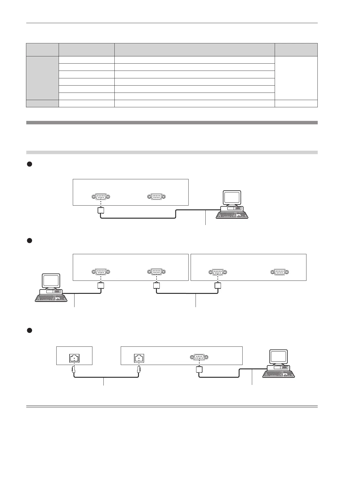
<SERIAL IN>/<SERIAL OUT> terminal
The <SERIAL IN>/<SERIAL OUT> terminal of the projector conforms with RS-232C so that the projector can be connected to and controlled
from a computer.
Connection
Projector connecting terminals
Computer
D-Sub 9p (female) D-Sub 9p (male)
D-Sub 9p (male)
Communication cable (straight)
Single projector
Multiple projectors
Connecting terminals on projector 2
D-Sub 9p (female) D-Sub 9p (male)
D-Sub 9p (female) D-Sub 9p (male)
Connecting terminals on projector 1
Computer
D-Sub 9p (male) D-Sub 9p (female)
D-Sub 9p (male)
Communication cableCommunication cable
DIGITAL LINK compatible device
Computer
D-Sub 9p (female)
Projector connecting terminals
DIGITAL LINK DIGITAL LINK
D-Sub 9p (male)
Communication cable (straight)
To connect to DIGITAL LINK compatible devices
LAN cable (straight)
Note
f The destination of [RS-232C] (x page 119) must be set according to the connection method.
f When connecting by a DIGITAL LINK compatible device, set the [PROJECTOR SETUP] menu → [STANDBY MODE] (x page 116) setting
to [NORMAL] to control the projector during standby.
When [STANDBY MODE] is set to [ECO], the projector cannot be control during standby.

 Loading...