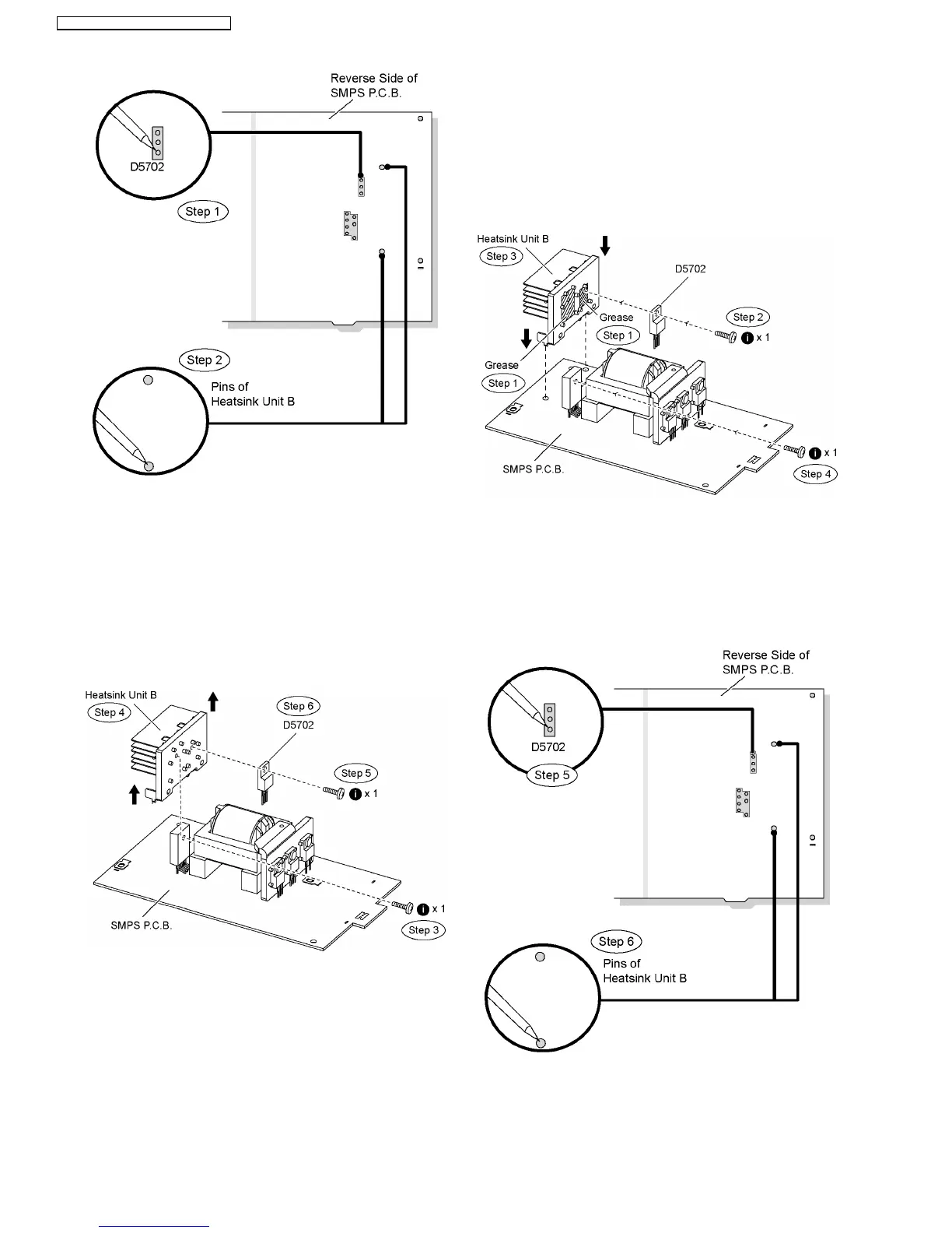
Step 3 Remove 1 screw from the switch regulator IC (IC5701).
Step 4 Remove the heatsink unit B in the direction of arrows.
Step 5 Remove 1 screw from the switch regulator diode.
(D5702).
Step 6 Remove the switch regulator diode (D5702) from the
heatsink unit B.
Caution: Handle the heatsink unit B with caution due to its
high temperature after prolonged use. Touching it may
lead to injuries.
Note : Refer to the diagrams of SMPS P.C.B. (Item 20.5) for
location of the part.
9.22.1. Assembly of Switch Regulator
Diode (D5702)
Step 1 Apply grease to the heatsink unit B.
Step 2 Fix and screw the switch regulator diode (D5702) to the
heatsink unit B.
Special Note: Ensure the switch regulator diode (D5702) is
tightly screwed to the heatsink unit B.
Step 3 Fix the heatsink unit B on SMPS P.C.B. in the direction
of arrows.
Step 4 Fix and screw the switch regulator IC (IC5701) to the
heatsink unit B
Special Note: Ensure the heatsink unit B is properly seated on
SMPS P.C.B.
Step 5 Solder pins of the switch regulator diode (D5702) on the
reverse side of SMPS P.C.B.
Step 6 Solder pins of the heatsink unit B on the reverse side of
SMPS P.C.B.
Special Note: Ensure pins of the switch regulator diode
(D5702) are properly seated and soldered on SMPS P.C.B.
58
SA-PT560E / SA-PT560EB / SA-PT560EG