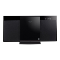
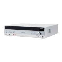
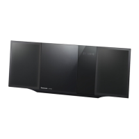
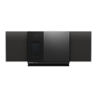
SC-HM910/SC-HM810
36
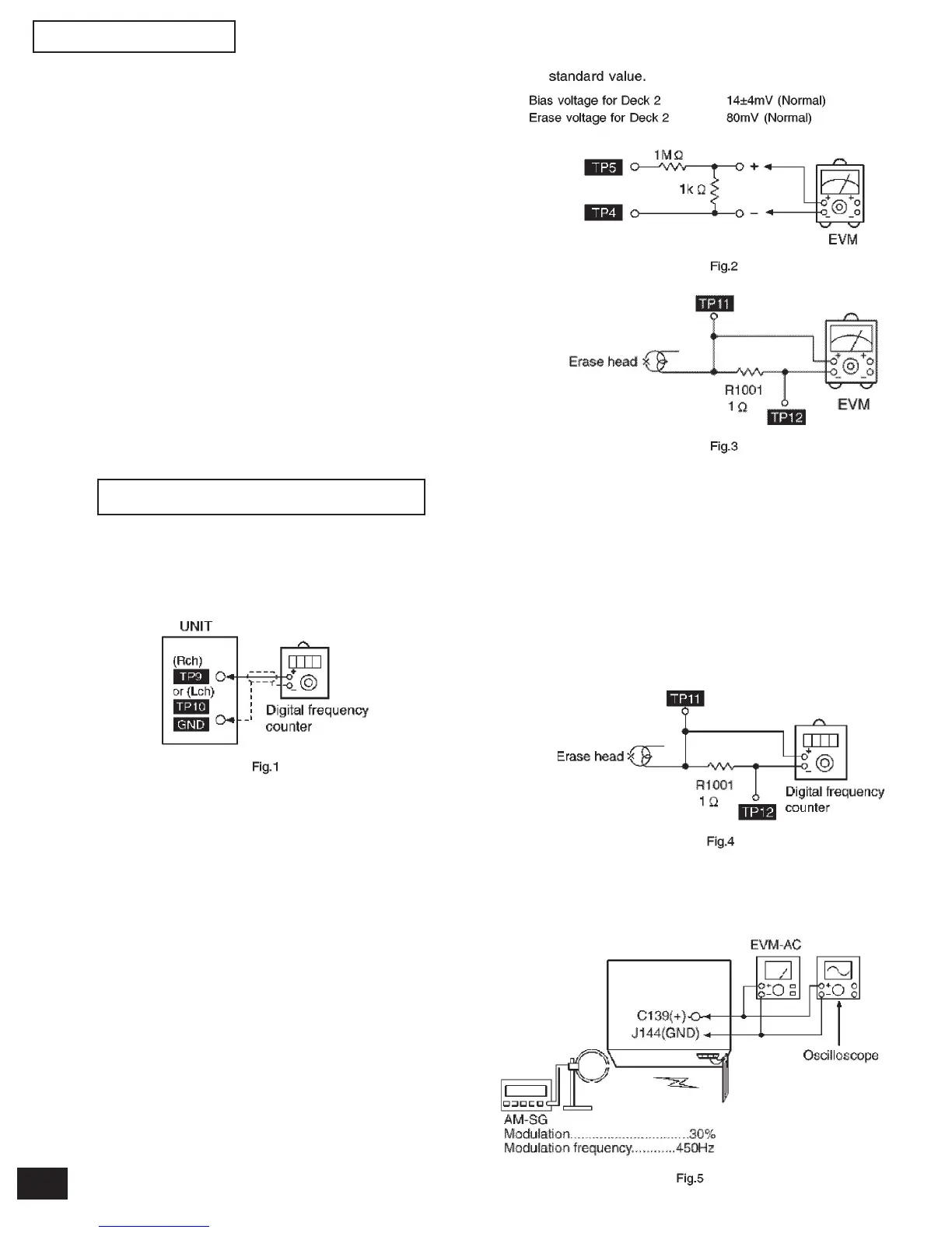
12.1.1.Tape Speed Adjustment
(Deck 1/2)
1. Set the tape edit button to “NORMAL” position.
2. Insert the test tape (QZZCWAT) to DECK 2 and play-
back (FWD side) the middle portion of it.
3. Adjust Motor VR (DECK 2) for the output value shown
below.
Adjustment target: 2940 ~ 3060 Hz (NORMAL speed)
4. After alignment, assure that the output frequency of
the DECK 1 FWD is within ± 60 Hz of the value of the
output frequency of DECK 2 FWD.
12 Measurements and Adjustments
12.1. Cassette Deck Section
• Measurement Condition
- Make sure head, capstan and press roller are clean.
- Judgeable room temperature 20 ± 5°C (68 ± 9°F)
• Measuring instrument
- EVM (DC Electronic Volmeter)
- Digital frecuency counter
• Test tape
- Tape speed gain adjustment (3 kHz, -10 dB); QZZCWAT
12.1.2.Bias and Erase Voltage
Check
1. Set the “AUX” position.
2. Insert the Normal blank tape (QZZCRA) into DECK 2
and the unit to “REC” mode (use “ REC/STOP” key).
3. Measure and make sure that the output is within the
standard value.
12.1.3.Bias Frequency Adjust-
ment (Deck 1/2)
1. Set the unit to “AUX” position.
2. Insert the Normal blank tape (QZZCRA) into DECK 2
and set the unit to “REC” mode (use “ REC/STOP”
key).
3. Adjust L1002 so that the output frequency is within
the standard value.
12.2 Tuner Section
12.2.1.AM-IF Alignment
1. Connect the instrument as shown in Fig. 5.
2. Set the unit to AM mode.
3. Apply signal as shown in Fig. 5 from AM-SG
4. adjust Z102 so that the output frequency is maximized
in Fig. 6.