SC-HM910/SC-HM810
26
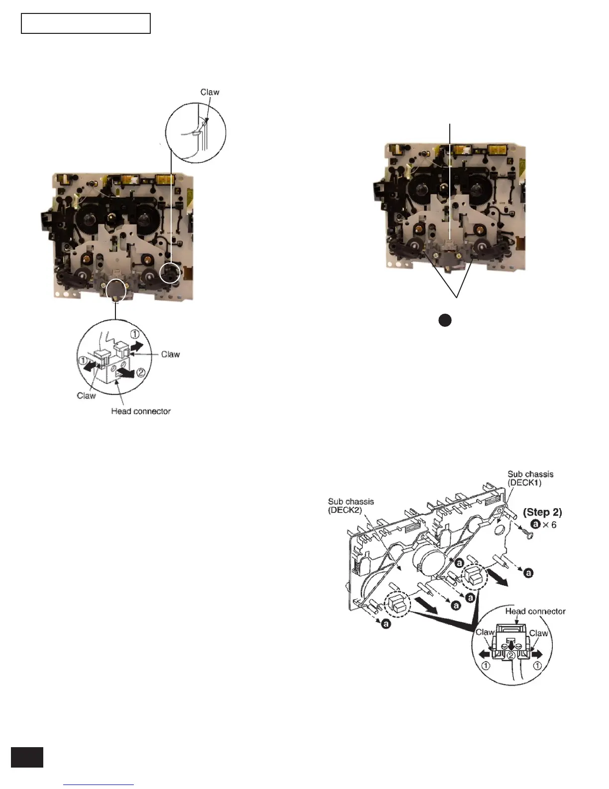
Step 11 Remove 4 screws.
Step 12 Remove mechanism Deck P.C.B.
* The mechanism as shown below is for DECK 1. For the one of
DECK 2, perform the same procedures.
Step 13 Release the 2 claws, and then remove the pinch roller
(R), (F).
Step 14 Release ther 2 claws, and then remove the head con-
nector.
7.9. Replacement for the CD motor ass’y. capstan belt A, capstan belt B
and winding belt
• Follow the (Step 1) - (Step 2) of item 7.1
• Follow the Disassembly for the CD Changer of item 7.2.
• Follow the (Step 1) - (Step 14) of item 7.4.
• Follow the (Step 1) - (Step 11) of item 7.9
Step 1 Release the 2 claws, and then remove the head con-
nector.
Step 2 Remove 6 screw.
Step 3 Remove the sub chassis
Pinch roller ass’y (R)
(RXL0125)
(Head Blook
DECK1: RED0063-1
DECK2: RED0074-1)
(Step 15)
a x 2
Step 15 Remove 2 screws.