When FA06=0, the higher feedback value is, the higher the motor speed is. This is positive
feedback.
When FA06=1, the lower the feedback value is, the higher the motor speed is. This is negative
feedback.
FA07 Sleep function selection Setting range:
0: Valid
1: Invalid
Mfr’s value: 1
When FA07=0, if inverter runs at the min frequency FA09 for a period time set by FA10, inverter
will stop.
When FA07=1, the sleep function is invalid.
FA09 Min frequency of PID adjusting (Hz) Setting range:
F112~F111
Mfr’s value: 5.00
The min frequency is set by FA09 when PID adjusting is valid.
FA10 Sleep delay time (S) Setting range:
0~500.0
Mfr’s value: 15.0
FA11 Wake delay time (S) Setting range:
0.0~3000
Mfr’s value: 3.0
FA18 Whether PID adjusting target is changed
0: Invalid
1: Valid
Mfr’s value: 1
When FA18=0, PID adjusting target cannot be changed.
FA19 Proportion Gain P Setting range: 0.00~10.00 Mfr’s value: 0.3
FA20 Integration time I (S) Setting range: 0.1~100.0 Mfr’s value: 0.3
FA21 Differential time D (S) Setting range: 0.0~10.0 Mfr’s value: 0.0
FA22 PID sampling period (S)
Setting range:0.1~10.0
Mfr’s value: 0.1
Increasing proportion gain, decreasing integration time and increasing differential time can
increase the dynamic response of PID closed-loop system. But if P is too high, I is too low or D
is too high, system will not be steady.
PID adjusting period is set by FA22. It affects PID adjusting speed.
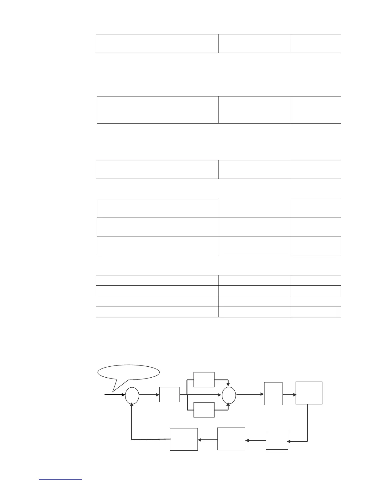
The following is PID adjusting arithmetic.

 Loading...


