COMPAX 1000SL Unit characteristics
45
Unit
hardware
Connector
assignment / cable
Technical dataConfigurationPositioning and
control functions
Optimization
functions
InterfacesAccessories /
options
StatusParameterError list
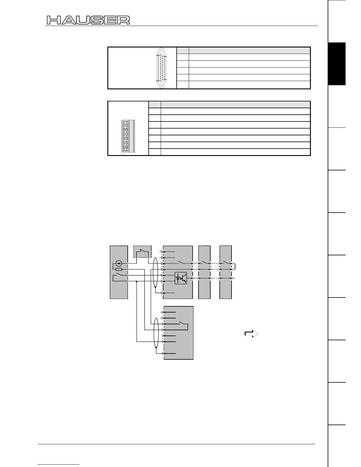
COMPAX 1000SL X19
Pin Assignment
23 +24V DC (<50mA)
10V
24 P: Ready contact
25 S: Ready contact
25 pin Sub-D
socket strip
screw connection
UNC4-40
14
25
1
13
11 Emergency stop input (activated by 15V – 24V)
Emergency stop input direct to COMPAX-M X9
Pin Assignment
1 +24V DC (<50mA)
20V
3 reserved
4 reserved
5 +24V DC – Output for emergency stop
6 Emergency stop input (activated by 15V – 24V)
Connector: Phoenix
MC1.5/7-ST-3.81
4567123
7 Screen
*
Emergency stop input on COMPAX-M
The emergency stop input on COMPAX-M X9 is enabled via parameter P219.
Meaning:
! P219="0": No emergency stop input on COMPAX-M X9
! P219="7": Emergency stop input on COMPAX-M X9 with the following data
! Stop with P10 as relative ramp time (P10 = braking time from 100% speed to
0%).
!
The motor is switched off.
!
Error message E56 is generated.
!
The ready contact drops.
Ready contact: max. 0.5A,
60V, 30W
control power supply
module
COMPAX-M
No. 1
COMPAX-M
No. x
external
component
X8/1
X8/2
X8/3
X8/4
X8/5
X8/6
X8/7
+24V
GND
shield
readiness
emerg. stop
X./1
X./2
X./3
X./4
X./5
X./6
X./7
+24V
GND
shield
COMPAX-S X9 i.e. COMPAX 35XXM X19
Applies to potential -
24V power supply.
Principle of safety
chain and
emergency stop
function

 Loading...


