EasyManuals Logo

Parker EX Series User Manual

Parker EX Series
133 pages
To Next Page IconTo Next Page
To Previous Page IconTo Previous Page
Page #120 background imageLoading...
Page #120 background image
120 Pvd3665_Gb_Ex_August 2022
3.10. Brake option
Caution: The holding brake is used to completely immobilize the servomotor
under load. It is not designed to be used for repeated dynamic braking ;
dynamic braking must only be used in the case of an emergency stop and
with a limited occurance depending on the load inertia and speed.
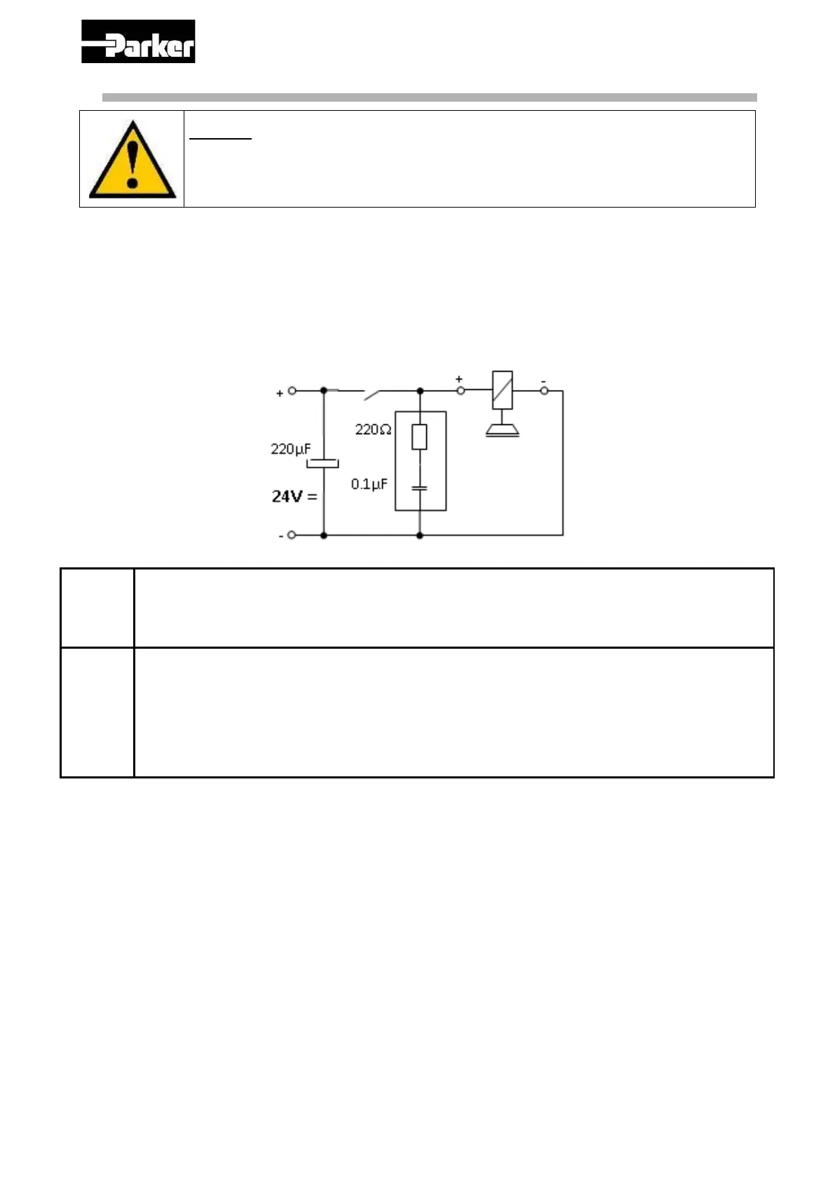
The standard brake power supply is 24 Vcc DC ± 10%.
Follow the polarity and the permissible voltage, and use shielded cables.
A 220 µF capacitor avoids untimely braking if the 24 V voltage is disturbed by the external
relay. Check the voltage value once this capacitor has been fitted. The RC network (220 Ω,
0.1 µF) is needed to eliminate interference produced by the brake coil.
Position the contactor in the DC circuit to reduce brake response times. Follow the
connection instructions taking the brake polarisation into account.
Motor
Static
torque
@20°C
Static
torque
@100°C
Power
Engaging
time
Disengaging
time
Extra Inertia
Angular
backlash
(N.m)
(N.m)
(W)
(ms)
(ms)
(Kg.m².10
-5
)
(°)
EX3
2
1.8
11
13
25
0.68
0
EX4
5.5
4
12
17
35
1.8
0
EX6
12
8
18
28
40
5.4
0
EX8
36
32
26
45
100
55.6
0
Table with typical values

Table of Contents

Questions and Answers:

Question and Answer IconNeed help?

Do you have a question about the Parker EX Series and is the answer not in the manual?

Parker EX Series Specifications

General IconGeneral
Fuel TypeGasoline
Control TypeElectronic
Valves per Cylinder4
Fuel SystemFuel Injected
Bore x Stroke86 mm x 86 mm

Related product manuals