107 – Pvd3665_Gb_Ex_August 2022
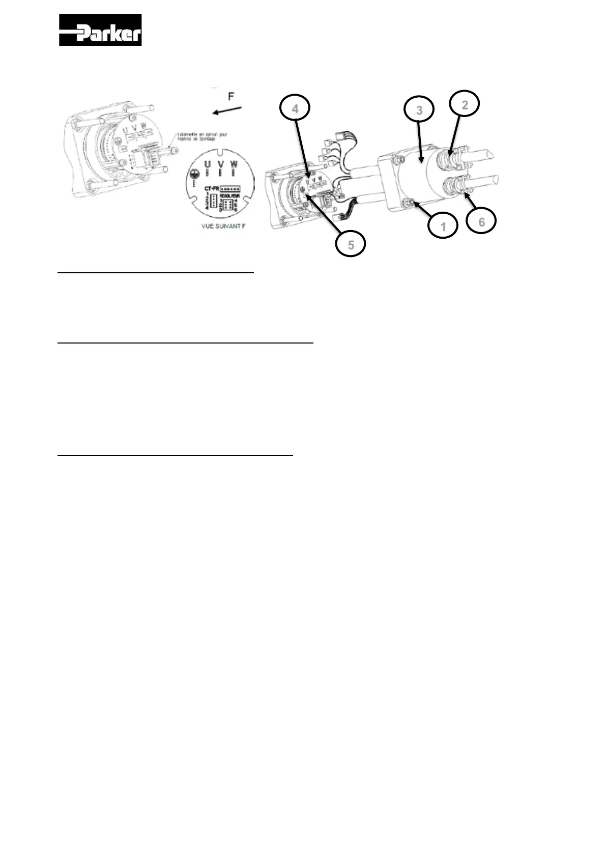
3.8.6.2. Connection of the feedback and power cable with connector on
EX3 :
Step 1 – Remove the rear cover :
1. Unscrew the 4 nuts Ref 1.
2. Unscrew the cable gland caps Ref 2.
3. Remove the cover Ref 3.
Step 2 – Connection of the feedback cable :
1. Insert the cable in the cable gland Ref 2.
2. Strip the wires on 3 mm and crimp them in the connector.
3. Plug the connector in the terminal of the PCB Ref 4 .
4. Crimp the shielding wire in the connector and plug the connector in the terminal Ref
5.
5. If the shielding connection is not necessary, cut the wire short the cable.
Step 3 – Connection of the power cable :
1. Insert the cable in the cable gland Ref 2.
2. Strip the wires on 3 mm and crimp them in the connector.
3. Put the wires U, V, W, Ground, TH+ and TH- and also BR+ and BR- in a case of a
motor with a brake equiped with their connectors on the terminal of the PCB Ref 4.
4. Crimp the shielding wire in the connector and place the connector in the terminal
Ref 5.
5. If the shielding connection is not necessary, cut the wire short the cable.

 Loading...


