109 – Pvd3665_Gb_Ex_August 2022
3.8.7. EX3-EX4 UL connection
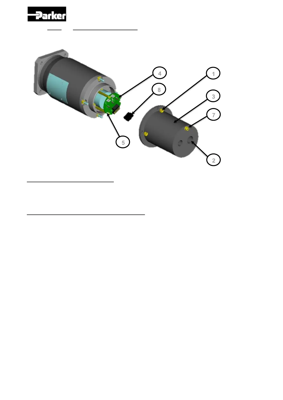
3.8.7.1. Connection of the feedack and power cable with connector:
Step 1 – Remove the rear cover:
1. Unscrew the 4 nuts Ref 1.
2. Unscrew the cable gland caps Ref 2.
3. Remove the cover Ref 3.
Step 2 – Connection of the feedback cable :
1. Insert the cable in the cable gland or conduit stop Ref 2.
2. Strip the wires on 3 mm and crimp them on the contacts supplied in the terminal
part kit with the manual crimp tooling Molex N°0638190000 for wire diameter AWG
20-24.
3. Place the contacts in the connector Ref 8.
4. Place the connector inside the PCB connector Ref 4.
5. Crimp the shielding wire in the connector and plug the connector in the terminal Ref
5.
6. If the shielding connection is not necessary, cut the wire short the cable.

 Loading...


