38
negative pole with black wire)
Note: The data are for reference only.
Check engine startup switch
Check the conductivity of the engine startup switch. If it is not conductive, replace it.
Note: See wiring diagram for startup switch status,
Check engine stop switch
Check the conductivity of the engine stop switch. If it is not conductive, replace it.
Remove the locking plate: Conducting
Install locking plate: Non-conducting
Press the button: Conducting
Detection of starting relay
1. Connect the brown lead to the positive electrode of the battery.
2. Connect the black lead to the negative electrode of the battery.
3. Check the conductivity between relay terminals. If it is not conductive, replace the relay.
4. Disconnect the lead connection with the battery and check the conductivity between the
relay terminals. If it is conductive, replace the relay.
Detection of magneto coil
Measure the peak voltage of magneto coil (between green wires).
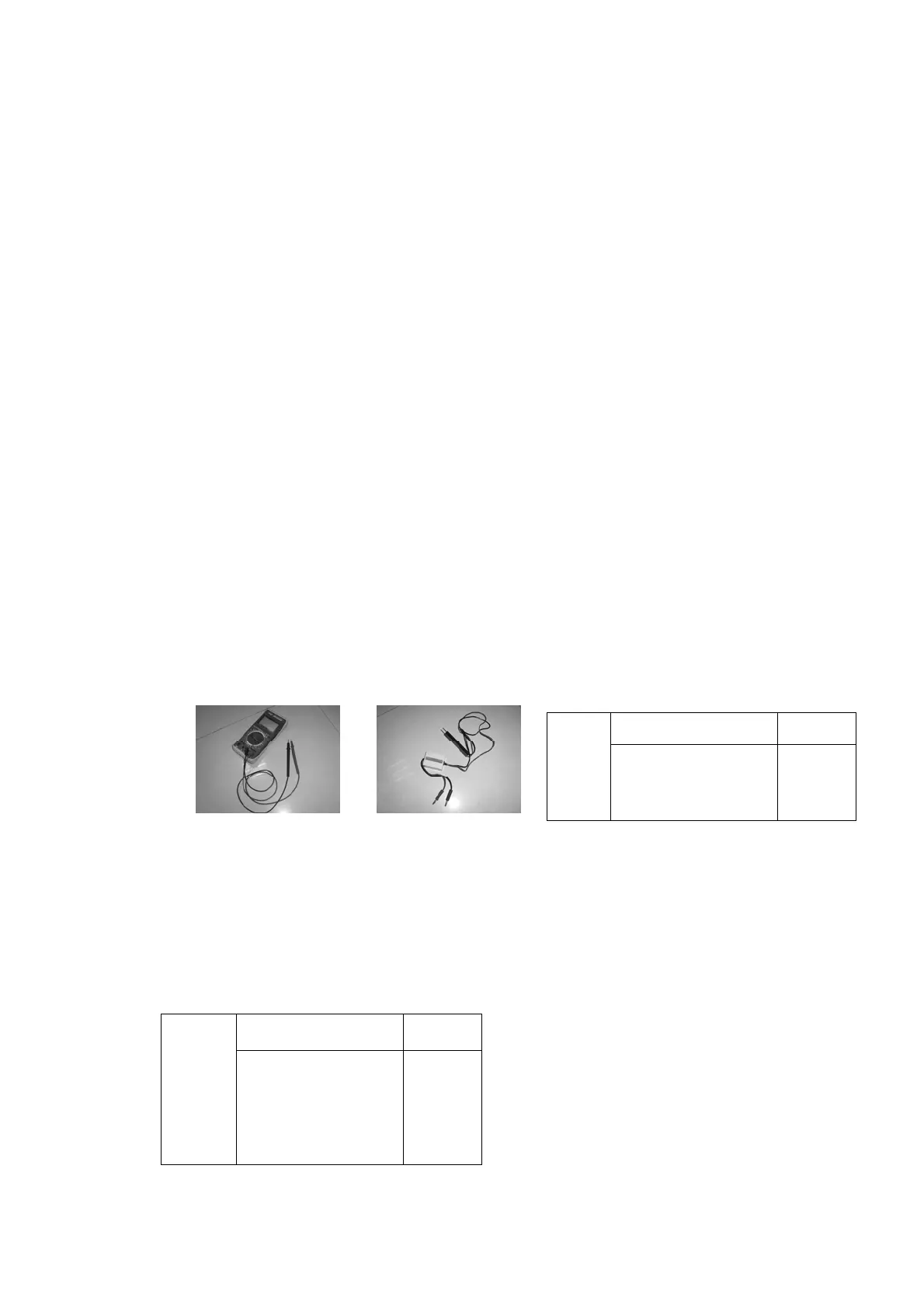
Use digital multimeter and peak voltage adapter to measure the peak output voltage of
the coil. If it is lower than the specified value, replace the magneto coil.
Detection of rectifier regulator
Measure the peak voltage (DC) of the rectifier regulator.
Open the rectifier output (red wire and black wire) and use a digital multimeter to measure
the voltage between the red wire and black wire at the rectifier regulator output.
If it is lower than the specified value, check the peak output voltage of magneto coil. If the
peak output voltage of magneto coil is higher than the specified value, replace the rectifier
regulator.
Peak
voltage
of
magnet
o coil
1500 r/min (no-load
53V
3500 r/min (no-load
115V
Peak
voltage
of
rectifier
regulator
1500 r/min (load) 14.5V
3500 r/min (load) 14.5V