Do you have a question about the Parsun F60 and is the answer not in the manual?
Details about the serial number and its meaning, located on the engine's label.
Guidance on choosing the correct propeller for optimal engine performance and load conditions.
Safety regulations and precautions to follow during maintenance and repair operations.
Procedure for verifying fuel hose connection and fuel tank level before delivery.
Steps to check engine oil and gear oil levels using the dipstick and oil level plug.
Testing the functionality of the emergency stop switch and safety rope.
Procedure for initial engine break-in, specifying RPM and duration for different hours.
Illustrations and names of specialized tools required for maintenance and repair tasks.
Visual identification of testing equipment such as digital tachometers and multimeters.
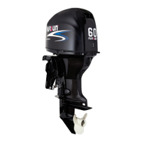
Comprehensive technical specifications including dimensions, weight, performance, and engine details.
Detailed repair data for engine components like cylinder head, block, oil ring, and camshaft.
Specifications and procedures for installing the lower casing unit, including backlash and shims.
Details on ignition timing, spark plug clearance, and component resistances for the electrical system.
Table of specified torque values for various engine and component fasteners during assembly.
Diagrams showing the external dimensions of the outboard motor for the D/T model.
Diagrams illustrating the external dimensions of the outboard motor for the CD/CT model.
Schedule of maintenance tasks based on operating hours and time intervals.
Procedures for inspecting and maintaining the fuel system components like tank, pump, and filter.
Instructions for checking and replacing engine oil, including oil level and oil change procedures.
Method for checking and adjusting valve clearance when the engine is cold.
Steps for checking and adjusting the throttle cable for proper operation.
Procedure for checking the smoothness of gear shifting and alignment of the shift linkage.
Instructions for checking and changing the gear oil in the lower casing unit.
Routine checks for anodes, lubrication points, cooling water channels, and thermostat.
Safety precautions and general notes for working on the ignition system.
Exploded view of the flywheel and related components with part numbers.
Exploded view of the engine's electrical components with numbered parts.
Exploded view of the fuel system components, including fuel pump, filter, and lines.
Exploded view of the engine block and related components, including torque specifications.
Schematic illustrating the electrical connections between various components of the outboard motor.
Detailed wiring diagram for starting systems.
Procedure for checking spark plug ignition by observing the spark.
Procedure for testing the ignition coil's primary and secondary resistance.
Measuring trigger coil peak voltage and resistance for troubleshooting ignition issues.
Measuring the rectifier regulator's peak voltage output (DC).
Table listing fault types, failure items, and their corresponding diagnostic codes.
Procedure for safely releasing fuel pressure before system maintenance.
Steps to remove and inspect the fuel joint for any damage or leaks.
Detailed procedure for removing and testing the fuel pump for leaks and proper operation.
Inspection of the fuel filter for blockages, damage, or leaks.
Safety precautions for preventing accidental starting during engine repair.
Exploded view of the engine's valve train components.
Exploded view of the crankshaft, connecting rods, and pistons.
Exploded view of the timing belt, pulleys, and related components.
Illustrations of specialized tools used for engine maintenance.
Procedure for measuring engine compression pressure using a pressure gauge.
Method for checking the engine's oil pressure with a manometer.
Step-by-step instructions for disassembling the engine.
Procedure for disassembling and checking the cylinder head components.
Checking camshaft size, roundness, journal diameter, and oil clearance.
Procedure for trimming valve seat rings using specific cutters to adjust sealing surface width.
Instructions for assembling the cylinder head, including camshaft and oil pump.
Measuring piston outer diameter, pin bore, and calculating taper/roundness limits.
Checking piston ring dimensions and end clearance.
Measuring crankshaft journal diameter, crank pin diameter/width, and checking runout.
Checking engine body and base for damage and cleaning cooling water channels.
Decomposition schematic diagram of the top cowling assembly.
Steps for disassembling and inspecting the top cowling and its components.
Exploded view of the bottom cowling assembly.
Exploded view of the throttle and shift control mechanisms.
Procedure for disassembling and checking the throttle and shift control components.
Exploded view of the steering handle assembly.
Procedure for disassembling and checking the steering handle components.
Exploded view of the upper casing unit and bracket assembly.
Exploded view of the oil pan assembly.
Procedure for disassembling and checking the bracket and absorber components.
Steps for disassembling and checking the water unit components.
Exploded view of the manual tilting device.
Procedure for disassembling the manual tilting device.
Procedure for disassembling the hydraulic tilting device.
Steps for checking oil level and venting air from the hydraulic tilting device.
Exploded view of the lower casing part for the D/T model.
Exploded view of the lower casing part for the CD/CT model.
Procedure for disassembling and checking the water pump components.
Checking the claw clutch and propeller shaft for damage or wear.
Steps for installing the clutch spring, claw clutch, and clutch ring.
Checking bearings, oil seals, and the casing cover for damage.
Procedure for installing casing cover oil seals and bearings.
Checking the drive shaft for bending or wear.
Checking the shift cam for wear or deformation.
Checking forward gear, reverse gear, and pinion for wear or damage.
Checking the forward gear bearing for rust and noise.
Checking the lower casing unit casing for cracks or blockages.
Installing bearings, drive shaft, gears, and pinion.
Installing the lower casing unit, checking shift operation, and injecting gear oil.
Adjusting shims as required when assembling the lower casing unit.
Explanation of deviation value marks on the lower casing unit.
Procedure for selecting and installing pinion shims.
Procedure for selecting and installing shims for the forward gear.
Procedure for selecting and installing shims for the reverse gear.
Troubleshooting common causes and solutions for engine starting failures.
Diagnosing and resolving issues with abnormal engine idling or stalling.
Identifying and fixing causes of reduced engine power or performance.
Troubleshooting common causes of excessive vibration in the outboard motor.
| Starting System | Electric |
|---|---|
| Full Throttle RPM Range | 5000-6000 RPM |
| Trim and Tilt System | Power Trim and Tilt |
| Power Output | 60 HP |
| Cooling System | Water-cooled |
| Max. Output | 60 HP |
| Steering | Remote |
| Recommended Fuel | Unleaded Gasoline (minimum RON 90) |
| Exhaust System | Through propeller |