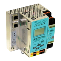
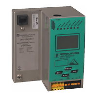
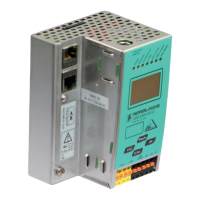
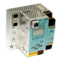
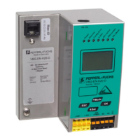
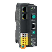
AS-i 3.0 PROFIBUS Gateway in Stainless Steel
Electrical connection
26.9.2013
27
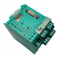
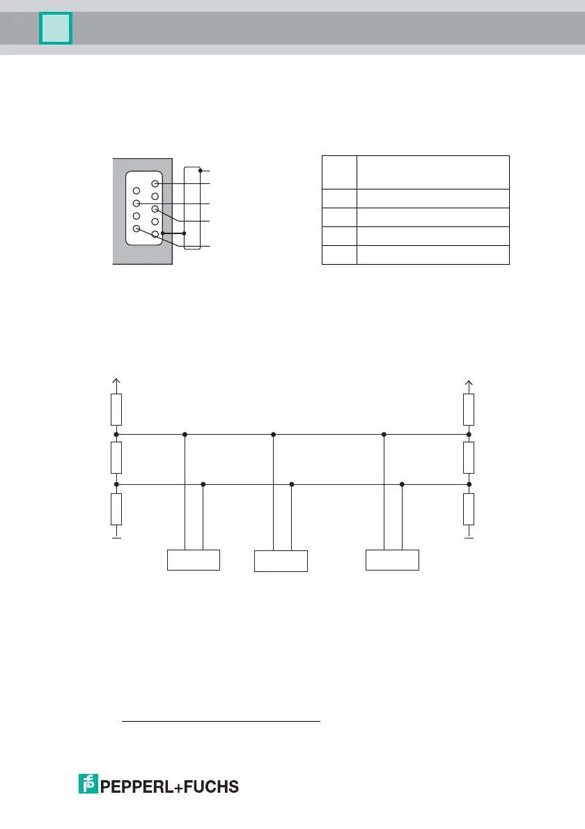
7.5 PROFIBUS interface
The PROFIBUS interface is designed as a 9-pin D-SUB connector, in accordance
with the PROFIBUS standard EN 50 170. It is located at the top left-hand side of
the master.
.
The AS-i/PROFIBUS gateway sends and receives signals on pins 3 and 8 of the
D-SUB connector. The PROFIBUS signal “RxD/TxD-N (data line A)
1
” is located
on pin 8, the signal “RxD/TxD-P (data line B)
1
” is located on pin 3.
Pin 5 (0 V) and pin 6 (5 V) supply 5 V DC for the bus termination resistor.
7.5.1 Terminating resistors on the PROFIBUS network
PIN Designation of the D-SUB
connector
Pin 3 Data line B („RxD/TxD-P“)
Pin 5 DGND (0 V)
Pin 6 VP / +5 V
Pin 8 Data line A („RxD/TxD-N“)
1. If you measure the DC voltage between RxD/TxD-P (data line B) and RxD/TxD-N (data line A), RxD/TxD-
P (data line B) is the positive pole when the bus is silent.
PROFIBUS
DGND (0 Volt)
RxD/TxD-N
(data line A)
RxD/TxD-P
(data line B)
VP / +5 Volt
5
4
3
2
1
9
8
7
6
A
B
B
B
390 Ω
220 Ω
390 Ω
Host
AS-i Master
390 Ω
220 Ω
390 Ω
5V 5V
GND GND
AS-i Master
AA