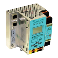
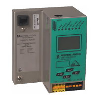
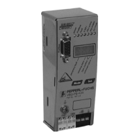
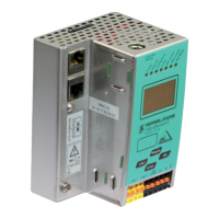
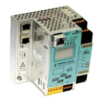
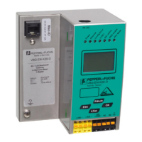
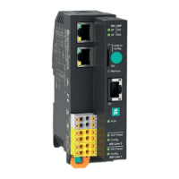
AS-i 3.0 PROFIBUS Gateway in Stainless Steel
Appendix: Example for startup on a Siemens S7
26.9.2013
61
Once the AS-i circuit has been configured and parameterized as desired, apply
this configuration to the VBG-PB-K30-D-S using the function "QUICK SETUP".
The VBG-PB-K30-D-S is now ready to run.
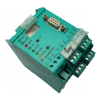
12.1.2 Electrical connection for PROFIBUS DP
To connect the VBG-PB-K30-D-S to the CPU 315-2DP, a standard PROFIBUS
cable with 9-pin SUB-D plug is used.
If the VBG-PB-K30-D-S is connected on the PROFIBUS as the last station, the
termination resistor on the PROFIBUS plug must be enabled.
12.2 SIMATIC Step 7 Configuration
The remainder of this description presumes that a SIMATIC Step7 project has
been created and added to an S7-300.
Now the hardware configuration must be opened for this SIMATIC-300 station.
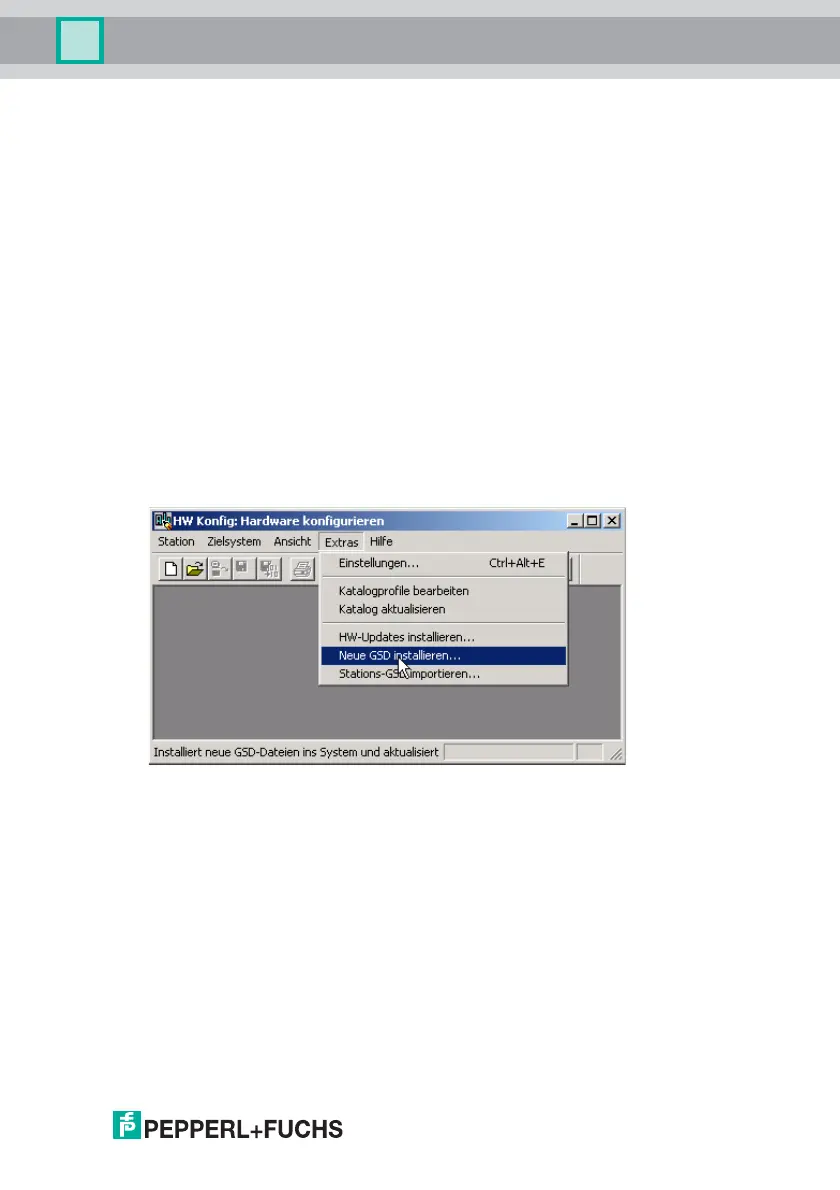
12.2.1 Configuration of the Hardware
Before configuring the hardware, the GSD file VBG-PB-K20-DMD 576 A1745.gsd
supplied with the VBG-PB-K30-D-S must be added to the hardware catalog.
Add the GSD file using the menu function "Install new GSD".
The PROFIBUS properties of the VBG-PB-K30-D-S are described in the GSD file
VBG-PB-K20-DMD 576 A1745.gsd.