AS-i 3.0 PROFIBUS Gateway in Stainless Steel
Appendix: Example for startup on a Siemens S7
26.9.2013
77
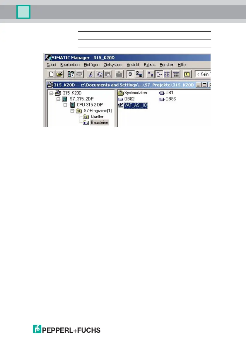
12.2.6 Variable table VAT_ASI_IO
In the hardware configuration the 16 bytes of I/O data for the AS-i/DP Gateway
are coupled to the input/output byte Address 2 to 17 of the process image. The di-
rectly send AS-i diagnostic information for error processing are evident from the
input bits of the EW0.
Flags + Fault Detector
Bit 0 = Configuration error
Bit 1 = Slave with address ZERO detected
Bit 2 = Automatic addressing not possible
Bit 3 = Automatic addressing available
Bit 4 = Projecting mode active
Bit 5 = Not in normal mode
Bit 6 = AS-i Power Fail
Bit 7 = AS-i Master is offline
Bit 8 = Peripheral error
Bit 9 = reserved
Bit 10 = reserved
Bit 11 = reserved
Bit 12 = Earth fault
Bit 13 = Overvoltage
Bit 14 = Noise
Bit 15 = Double address
This allows the AS-i circuit data to appear directly in the process image inputs/
outputs.
OB100 Startup OB. This OB is run once when the CPU starts up.
VAT_ASI_IO Variable table, AS-i startup example.