Visual Inspection
Visually check the condition of all gauges, sensors,
and wiring. Look for wiring and components that are
loose, broken, or damaged. Damaged wiring or
components should be repaired or replaced
immediately.
i09415387
Engine Valve Lash - Inspect/
Adjust
(Valves and Valve Bridges)
Ensure that the engine cannot be started while
this maintenance is being performed. To help pre-
vent possible injury, do not use the starting motor
to turn the flywheel.
Hot engine components can cause burns. Allow
additional time for the engine to cool before
measuring/adjusting valve lash clearance.
NOTICE
Only qualified service personel should perform this
maintenance. Refer to the Service Manual or your au-
thorized Perkins dealer or your Perkins distributor for
the complete valve lash adjustment procedure.
Operation of Perkins engines with incorrect valve
lash can reduce engine efficiency, and also reduce
engine component life.
Note: The valve bridges must be equalized before
the valve lash is adjusted.
Record the valve clearance. Refer to Systems
Operation, Testing and Adjusting, “Valve Lash -
Adjust” for the correct procedure.
Note: The valve depth is to be measured at every
service. The valve recession can then be calculated.
A valve recession tool has been designed to give
service personnel a good indication of the cylinder
head valve recession or cylinder head valve seat
wear without the need to remove the cylinder heads.
Refer to Operation and Maintenance Manual,
Overhaul (Top End) or contact your Perkins
distributor for more information.
i09982246
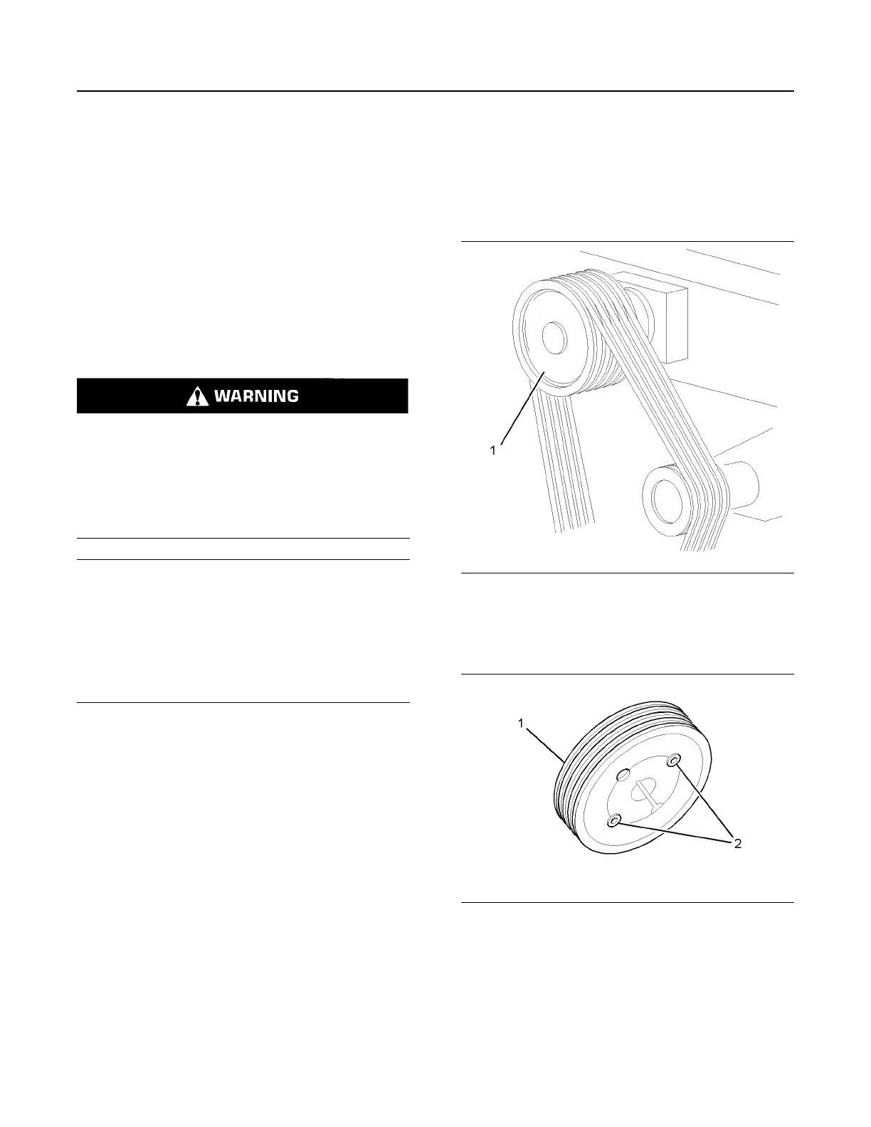
Fan Drive Pulley - Check
1. Isolate the electrical supply to the engine.
Illustration 93 g01238304
Typical example
2. Remove the guards (not shown) to gain access to
the fan drive pulley (1).
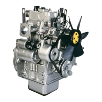
Illustration 94 g01238305
3. Tighten the grub screws (2) to a torque of 90 N·m
(66 lb ft).
4. Install the guards (not shown).
5. Restore the electrical supply to the engine.
M0163009 85
Maintenance Section
Engine Valve Lash - Inspect/Adjust