SUSPENSION
CAUTION
Completing this procedure will enable
you to safely reach the nearest au
-
thorized Peterbilt repair facility to have
ride height and pinion angle reset us
-
ing the proper equipment and tech-
nique. Do this as soon as possible to
avoid potential driveline damage.
NOTE
Suitable wheel chocks are at a mini-
mum an 18-inch (46 cm) long 4x4.
1. Ensure that the tractor is fully laden
during this procedure. Do not use
these procedures on a vehicle that is
not laden (bobtail).
2. Ensure the
air supply and delivery
plumbing of the height control valve
is consistent with the following
illustrations.
(04/13)
Typical Height Control Valve (Location
on Vehicle)
NOTE
• At least
one of the mounting holes
in the height control valve bracket
will be slotted to permit rotating
the valve.
• On dual
-valve systems, begin
with the LH valve on the next
step.
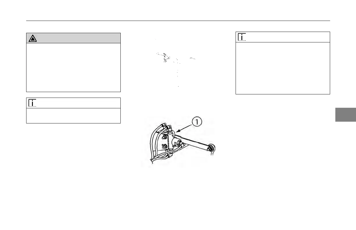
3. Loosen the
fasteners mounting a
height control valve to its bracket.
Typical Height Control Valve (Rear
View Looking Forward)
1. Alignment Dowel
Y53-6047–2C 4-49
4