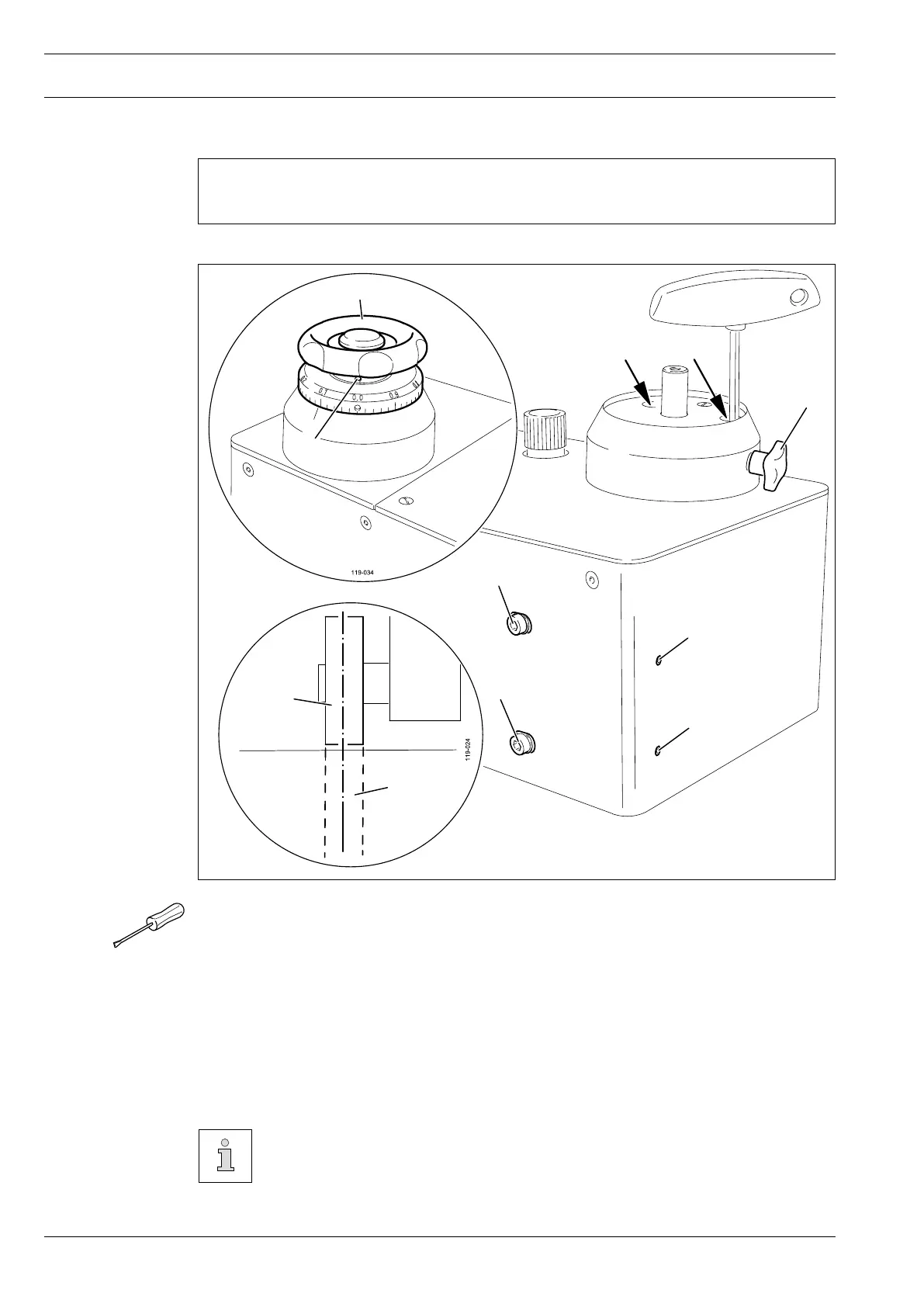
13.07 Position of the feed rollers to each other
Tighten screw 1.
Remove balance wheel 2 (screw 3).
Loosen two screws 4 on the bearing of the top feed roller with an Allen key (jaw width 5,
accessible through holes in the case).
Adjust screws 5 and screws 6 in accordance with the requirement.
Tighten screws 4 and 5.
Fit balance wheel 2 (screw 3) and loosen screw 1.
Check the feed roller clearance, see Chapter 9.01 Adjusting the feed roller clearance.
It is possible to check that the feed rollers are parallel to each other with a lay-
er of carbon paper between two layers of paper. For this purpose, use the “Tur-
ning the rollers” function, see Chapter 10.10 Turning the rollers.
●
●
●
●
●
●
●
Requirement
The feed rollers 7 should be centred and parallel to each other.
Fig. 13 - 04
6
6
5
5
1
4
4
2
3
7
7