Determining the horizontal mounting orientation of the turbopump
1. Always align the fore-vacuum connection downwards vertically.
–
Permissible deviation ± 25°
2. Support the tube connections in front of the turbopump.
3. Do not allow any forces from the piping system to act on the turbopump.
4. Do not load the high vacuum flange of the turbopump on one side.
5.2.6 Attaching ISO-K flange onto ISO-K
ISO flange connections
For the connection of flanges in ISO-KF or ISO-K design, twisting may occur in the event of
sudden blockage of the rotor, despite correct installation.
●
Leak-tightness of the flange connection, however, is not jeopardized in this regard.
Required tools
●
Wrench, WAF 15
●
Calibrated torque wrench (Tightening factor ≤ 1.6)
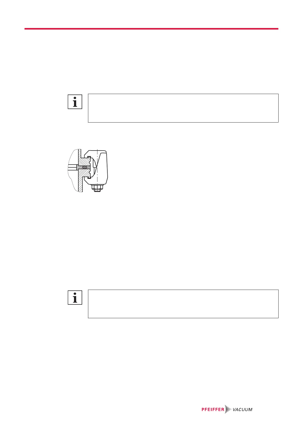
Fig. 9: Flange connection ISO-K to ISO-F, bracket screws
Connection with bracket screw
1. For the connection of the turbopump, use only the approved mounting kits from Pfeiffer Vacuum.
2. Connect the flange with the components of the mounting kit according to the figure.
3. Use for all prescribed components for the turbopump.
4. Tighten the bracket screws cross-wise in 3 steps.
–
Tightening torque: 5, 15, 25 ± 2 Nm
5.2.7 Attaching ISO-K flange to ISO-F
The connection types for ISO-K flange installation with ISO-F flange are:
●
"Hexagon head screw and tapped hole"
●
"Stud screw with tapped hole"
●
"Stud screw with through hole"
ISO flange connections
For the connection of flanges in ISO-KF or ISO-K design, twisting may occur in the event of
sudden blockage of the rotor, despite correct installation.
●
Leak-tightness of the flange connection, however, is not jeopardized in this regard.
Required tools
●
Hexagon wrench (15 WAF)
●
Calibrated torque wrench (tightening factor ≤ 1.6)
Installation
29/74