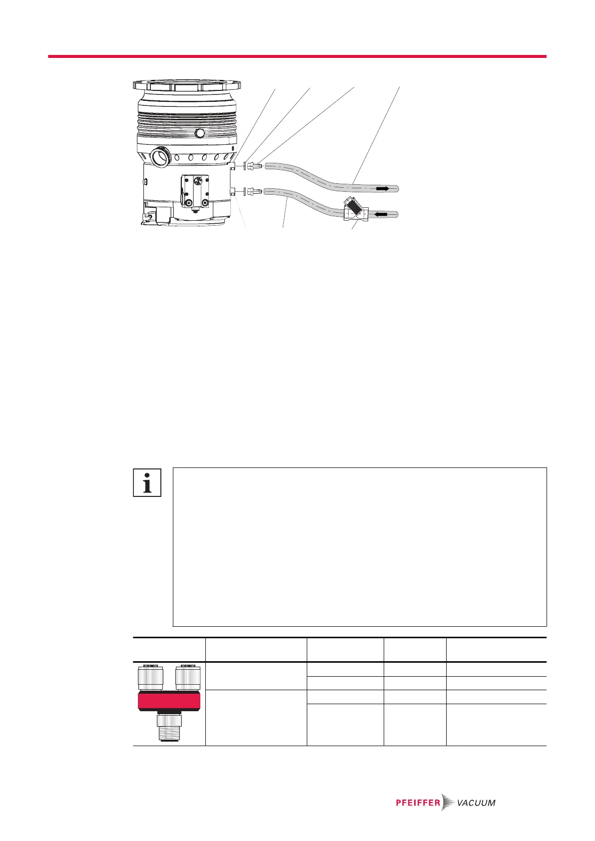
Fig. 23: Cooling water connection
1 Cooling water outlet, 1/4" thread 5 Dirt trap
2 Sealing ring (2x) 6 Feed line
3 Threaded nozzle (2x) 7 Cooling water inlet, 1/4" thread
4 Return line
Procedure
Pfeiffer Vacuum recommends the use of a dirt trap in the supply line.
1. Screw one hose nozzle with sealing ring onto each of the turbopump's cooling water connections.
–
Tightening torque: max. 15 Nm
2. Connect the cooling water supply line to the hose nozzle at the designated cooling water inlet of
the turbopump.
3. Connect the cooling water return line to the hose nozzle at the designated cooling water outlet of
the turbopump.
4. Secure the hose lines on the turbopump with hose clamps.
5.6 Connecting accessories
Electronic drive unit TC 1200 accessory connection
The electronic drive unit of the turbopump offers space for the connection of maximum 4
accessory devices. M12 sockets with the designation "accessory" are available for this pur-
pose.
●
The accessory connections have been preconfigured at the factory.
●
After connecting pre-configured accessory devices, these are immediately ready for
operation according to the factory settings.
●
The use of other accessories for turbopumps is possible and requires settings in the
configuration of the electronic drive unit.
●
The desired accessory output is configured via RS-485 using Pfeiffer Vacuum display
and control units or a PC.
●
You can find more detailed information in the “Electronic drive unit TC|1200” operating
manual.
Electronic drive unit
connection
Accessory con-
nection
Y-connector Pre-set configuration
1 2
1 2
Y-Connector
for Accessories
Acc. A A1 Y-1 Sealing gas valve
A2 Y-2 Backing pump
Acc. B B1 Y-1 Venting valve
B2 Y-2 Heating
Tbl. 11: Factory pre-set accessory connections on the electronic drive unit
Installation
37/74