CLASS NO.
All rights strictly reserved. Reproduction or issue
to third parties in any form whatever is not permitted
without written authority, from the proprietors. .
NAME
2838 100 05424
TY
CHECK
SUPERS.
DATE
Property of
PHILIPS ELECTRONICS INDUSTRIES (TAIWAN) LTD.-C.E.
10
A4
0.9 BDL3245E/BDL4245E/BDL4645E
32”/42”/46” FHD LCD PUBLIC DISPLAY
2011-07-01 PHILIPS Page 17 of 38
MMD Con
idential
• Video inputs: Composite/S-Video/Component/HDMI.
a、 AV input: VIDEO, S-Video and R/L Cinch audio in.
b、 Component input: YPbPr with R/L Cinch audio in.
c、 HDMI input: Type A includes digital video and audio, HDCP supported.
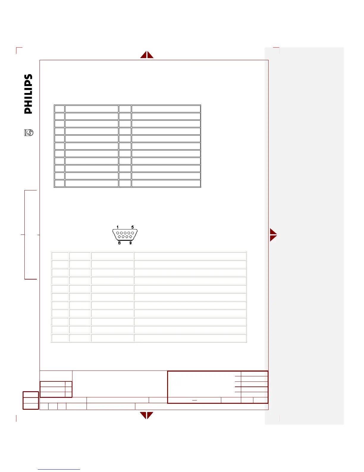
HDMI type A connector pin assignment:
Pin Signal Assignment Pin Signal Assignment
1 TMDS Data2+ 2 TMDS Data2 Shield
3 TMDS Data2– 4 TMDS Data1+
5 TMDS Data1 Shield 6 TMDS Data1–
7 TMDS Data0+ 8 TMDS Data0 Shield
9 TMDS Data0– 10 TMDS Clock+
11 TMDS Clock Shield 12 TMDS Clock–
13 CEC 14 Reserved (N.C. on device)
15 SCL 16 SDA
17 DDC/CEC Ground 18 +5V Power
19 Hot Plug Detect
• VGA D-Sub Out: For daisy chain purpose.
• Optional Slot: For the related Intel OPS devices plug in/out.
• AV Out: VIDEO and R/L Cinch audio out.
• Stereo audio output: 10W (at 8ohm) cinch audio stereo connector for stereo audio.
• Speaker output: 10W (at 8ohm) stereo output snap type connectors.
• RS232 In/Out: DB-9 RS232 male type connector.
DB-9 connector pin assignment:
DB-25 D-sub-9 Signal Direction Signal Name
1 x Protective Ground
2 3 DTE-to-DCE Transmitted Data
3 2 DCE-to-DTE Received Data
4 7 DTE-to-DCE Request To Send
5 8 DCE-to-DTE Clear To Send
6 6 DCE-to-DTE Data Set Ready
7 5 x Signal Ground
8 1 DCE-to-DTE Received Line Signal Detector (Carrier Detect)
20 4 DTE-to-DCE Data Terminal Ready
22 9 DCE-to-DTE Ring Indicator