M4735A Service Manual 4-57
Internal Assemblies - Top Case
4
b. Connect the large ribbon cable (connects to the Control PCA).
c. Connect the small 3-pin connector next to the ribbon cable.
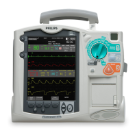
Figure 4-29 Removing the Parameter PCA
After Repair
After repairs are complete, perform the following steps.
1. Replace and connect the SpO
2
PCA.
See "SpO2 PCA" on page 4-58.
2. Reassemble the case.
See "Closing the Case" on page 4-99.
3. Restore the customer’s configuration.
Enter Configuration Mode and reload the customer’s configuration from
the data card, or reconfigure the unit, as needed. See "Configuration
Mode" on page 2-11.
4. Test performance.
Conduct Performance Verification Testing as described in "Performance
Verification and Safety Tests" starting on page 2-1.
Cable to
ECG
Connector
Flex Circuit to
SpO
2
Connector
Ribbon Cable to
Control PCA
Parameter PCA
SpO
2
Connector
ECG Out (Sync)
Connector

 Loading...