Do you have a question about the Philips HeartStart XL and is the answer not in the manual?
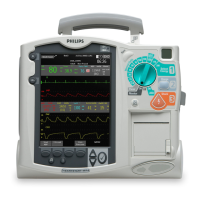
Service Manual for the M4735A HeartStart XL Defibrillator/Monitor.
Details about the manual's edition, publication, and content limitations.
Warning regarding RF interference affecting device performance.
Caution about using non-recommended accessories and device intended use.
Compliance with the Medical Device Directive and EU representative information.
Explains text conventions used in the manual for warnings, cautions, and notes.
Defines conventions for hypertext links used in the online version of the manual.
General information about the M4735A prior to servicing.
Information on accessing online service training for the device.
Describes the M4735A's capabilities and modes of operation.
Details about the rechargeable SLA battery used in the M4735A.
Mentions preventive maintenance is covered in the user manual's maintenance chapter.
Explains the subassembly replacement philosophy for the M4735A.
States the repair philosophy for the SLA battery is unit replacement.
Introduces tests and inspections to verify M4735A performance.
Categorizes testing requirements based on repair type.
Summarizes tests, procedures, expected results, and data recording.
Instructions for entering and using Configuration Mode for settings management.
Instructions for entering Diagnostic Mode for various tests.
Steps for using the tool to set language, enable SpO2, and program serial number.
Procedure for visually inspecting the unit, cables, and accessories.
Basic functional checks to verify unit performance.
Overview of diagnostic tests for major hardware components.
Covers electrical safety tests for the M4735A.
Information on troubleshooting M4735A problems.
Outlines the systematic approach to troubleshooting and repair.
Lists error codes, possible causes, and corrective actions.
Advises checking internal connections before replacing subassemblies.
Procedures for replacing defective subassemblies.
Provides guidance on how to use the troubleshooting tables.
Contact information for service assistance in the USA.
Contact information for service in various international locations.
Procedures for removing and replacing M4735A subassemblies.
Important points to keep in mind when servicing the M4735A.
Detailed steps for removing the printer assembly.
Detailed steps for removing the battery cover.
Methods for safely discharging power supply capacitors.
Steps to safely separate the unit's case halves.
Primary method for discharging the defibrillator capacitor using a tool.
Secondary method for discharging the defibrillator capacitor using clip leads.
Procedure for removing and replacing the lithium backup battery.
Steps for removing and replacing the Control PCA.
Steps for removing and replacing the Keyscan PCA.
Procedure for removing and replacing the Display Assembly.
Steps for removing and replacing the Battery PCA.
Procedure for removing and replacing the defibrillator capacitor.
Steps for removing and replacing the Power PCA.
Procedure for joining the top and bottom case halves.
Provides part numbers for replaceable assemblies and subassemblies.
Information on how to order replacement parts.
Information on key components requiring detailed tracking for failed and replacement assemblies.
Tables providing part numbers for electrical assemblies.
Tables providing part numbers for mechanical assemblies.
Lists part numbers for Language Support Tools by language.
Lists part numbers for upgrades, supplies, and accessories.
Lists key components, part numbers, and tracking methods.
Describes the internal operation of the M4735A at a functional-block level.
Describes functions handled by each Printed Circuit Assembly (PCA).
Describes how signals route through PCAs for major system functions.
Describes events that initiate a charging cycle for defibrillation.
Explains the process of initiating and delivering a shock.
Explains the types of audio output (tones and voice prompts).
Describes how display functions are handled by the Control PCA.
Describes how printing data is handled by the Control PCA.
Information on power supply and unit consumption.
Provides specifications, symbol definitions, safety, and EMC information.
Specifications for the defibrillator waveform and shock delivery.
Specifications for AED mode energy profile and shock series.
How the device evaluates patient ECG and connection impedance.
Describes ECG input sources (pads, leads) and available leads.
Details the digital readout range and accuracy for heart rate.
Provides dimensions of the display.
States the display resolution in pixels.
Specifies the battery type as 12V rechargeable Sealed Lead Acid (SLA).
Details approximate charge times to 90% and 100%.
How to start/stop strips and data included.
Explains symbols used on the monitor and printed strips.
Lists types of reports that can be printed.
Details the range and accuracy of pacing current.
Explains how SpO2 accuracy is expressed.
Operating and storage temperature ranges.
Compliance with safety standards.
Compliance with electromagnetic compatibility standards.
Displays defibrillator current waveform at 150J discharge into 25 ohms.
Displays defibrillator current waveform at 150J discharge into 50 ohms.
Displays defibrillator current waveform at 200J discharge into 25 ohms.
Lists meanings of symbols on the M4735A and M3516A battery.
General warnings for use by untrained personnel and during therapy delivery.
Guidance on identifying and mitigating RF interference sources.
Specifies immunity levels and performance degradation due to interference.
| Brand | Philips |
|---|---|
| Model | HeartStart XL |
| Category | Camera Accessories |
| Language | English |