Circuit Descriptions, Abbreviation List, and IC Data Sheets
EN 206 JL2.1E AA9.
9.3.9 Useful Data
See table below for the voltage specifications:
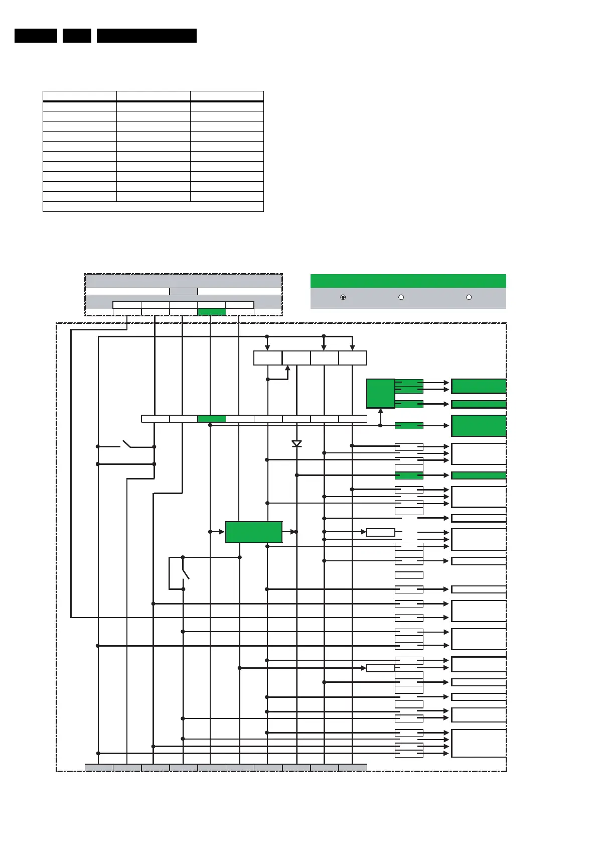
In the next figures an overview is given of the power distribution
in the different power states: STANDBY, SEMI-STANDBY, and
ON-mode.
Figure 9-10 Supply distribution: STANDBY Mode (mentioned values are indicative)
Voltage Name Value [V] Tolerance [%]
+5V2 5.2 5
+5V 5.1 5
+8V6 8.6 5
+12VS 12 5
+VTUN 33 5
+1V2 1.26 3
+2V5 2.6 4
+2V5D 2.6 (2.5) * 4 (5) *
+3V3 3.3 5
+5V2S 5.1 5
*) ON mode (STAND-BY mode)
F_15710_157.eps
200905
Su
l
d.c. power:
0.21 W
a.c. power:
0.83 W
Vtun +12VS +8V6 +5V2 +5V
power 0.00
0.00 0.00 0.21 0.00
(W)
DC-DC DC-DC DC-DC
12V/3.3V 12V/2.6V 12V/1.2V
(mA)
12
14
1
Serial Flash
(mA) 0 0 39 0 0 0 0 0
8
0
+12V switch 0
(by-passed)
0
4
Viper2 DDRs
0
0
0
0 PNX2015 DDR
+1.5V st. 0
0
+5V2S switch
0
(by-passed)
0
Spider DDR
0
NAND Flash
0
0
0
0
0
3V3 stab.
0
0
MOP
0
Ethernet
0 USB 2.0 controller
0+3 USB
orts
ext.
0
0
0
0
+12VSW +12VS +8V6 +5V2S +5V2 +5V +3V3 +2V5D +2V5 +1V2
JAGUAR ANALOG SUPPLY DISTRIBUTION IN STANDBY MODE
Jaguar Analog 2K5 SSB
+2V5D stabilizer
(standby mode)
Spider
LEDs + IR sensor
(ext. SSB)
Stdb uP
PNX2015
1.2V
and
3.3V
stabilizers
+2V5D
stabilizer
Viper2
Audio + I/O
PNX2015
MPIF1 + MPIF2
Tuner 1 +Tuner 2
HDMI
STANDBY ONSEMI-STANDBY