UART0 145 May 03, 2004
Philips Semiconductors Preliminary User Manual
LPC2119/2129/2194/2292/2294ARM-based Microcontroller
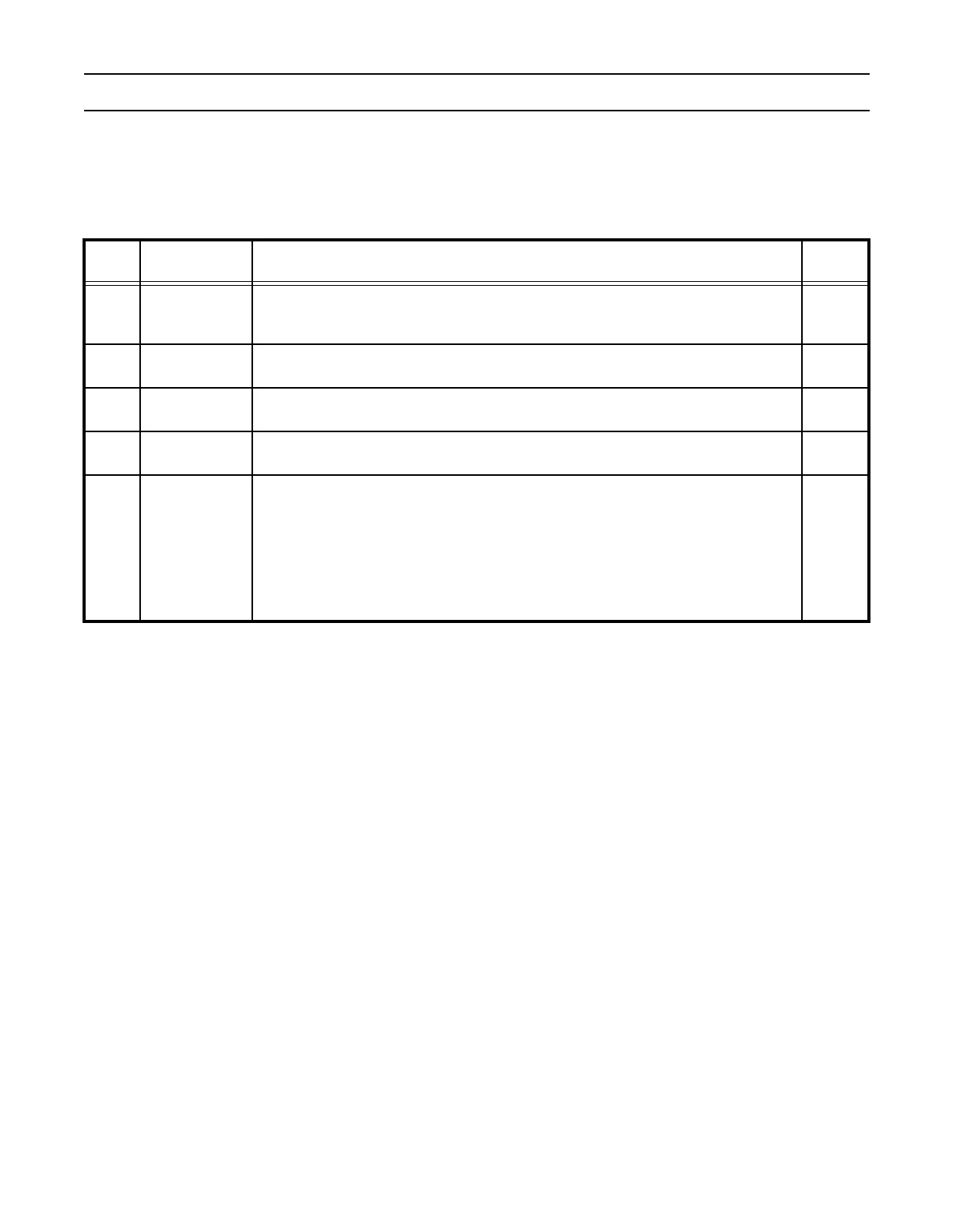
UART0 FIFO Control Register (U0FCR - 0xE000C008)
The U0FCR controls the operation of the UART0 Rx and Tx FIFOs.
Table 82: UART0 FIFO Control Register Bit Descriptions (U0FCR - 0xE000C008)
U0FCR Function Description
Reset
Value
0 FIFO Enable
Active high enable for both UART0 Rx and Tx FIFOs and U0FCR7:1 access. This bit
must be set for proper UART0 opearation. Any transition on this bit will automatically
clear the UART0 FIFOs.
0
1 Rx FIFO Reset
Writing a logic 1 to U0FCR1 will clear all bytes in UART0 Rx FIFO and reset the pointer
logic. This bit is self-clearing.
0
2Tx FIFO Reset
Writing a logic 1 to U0FCR2 will clear all bytes in UART0 Tx FIFO and reset the pointer
logic. This bit is self-clearing.
0
5:3 Reserved
Reserved, user software should not write ones to reserved bits. The value read from a
reserved bit is not defined.
NA
7:6
Rx Trigger Level
Select
00: trigger level 0 (default=1 character or 0x01h)
01: trigger level 1 (default=4 characters or 0x04h)
10: trigger level 2 (default=8 characters or 0x08h)
11: trigger level 3 (default=14 characters or 0x0eh)
These two bits determine how many receiver UART0 FIFO characters must be written
before an interrupt is activated. The four trigger levels are defined by the user at
compilation allowing the user to tune the trigger levels to the FIFO depths chosen.
0