I2C Interface 169 May 03, 2004
Philips Semiconductors Preliminary User Manual
LPC2119/2129/2194/2292/2294ARM-based Microcontroller
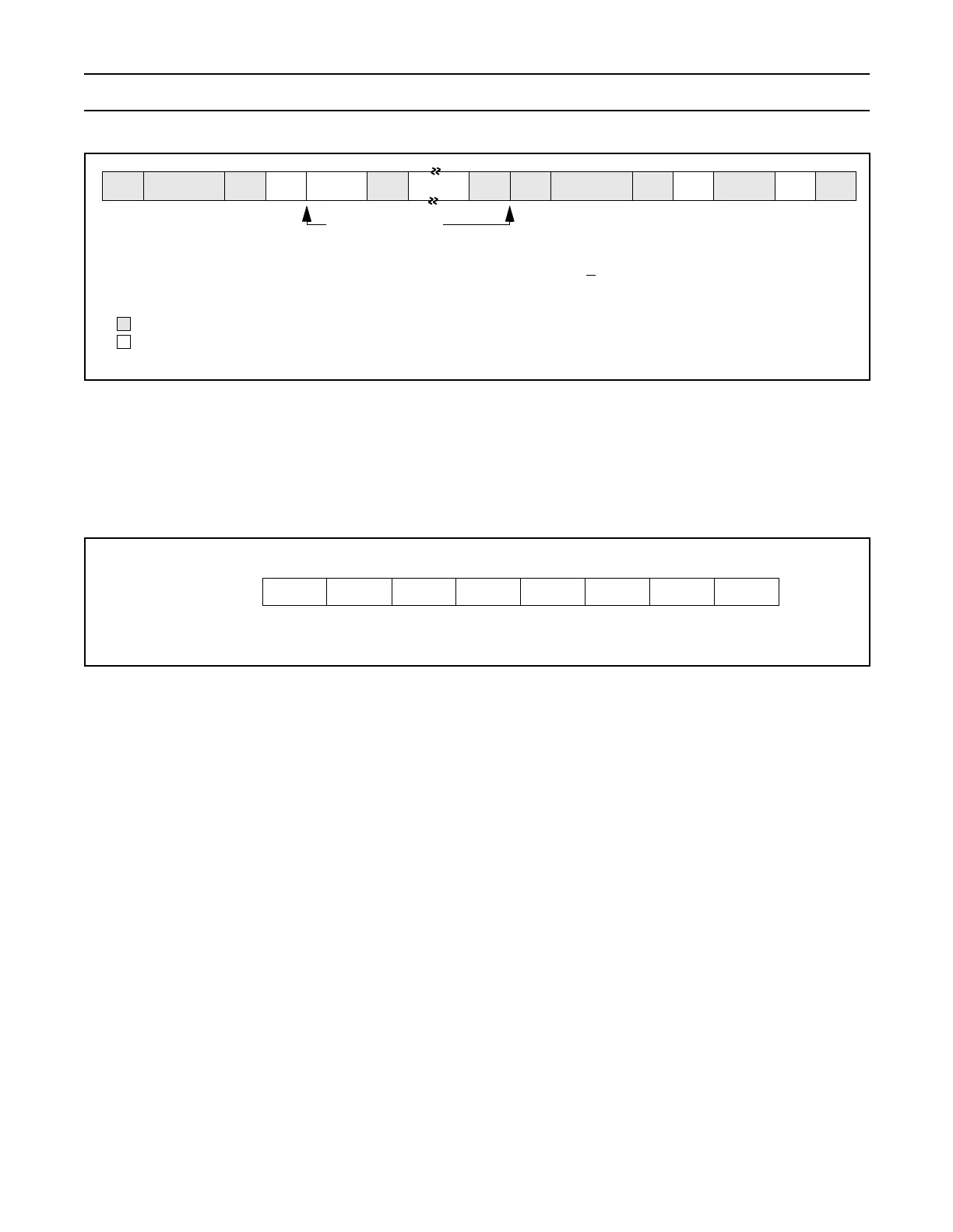
Figure 28: A master receiver switch to master transmitter after sending repeated START
Slave Receiver Mode:
In the slave receiver mode, data bytes are received from a master transmitter. To initialize the slave receiver mode, user should
write the Slave Address Register (I2ADR) and write the I
2
C Control Set Register (I2CONSET) as shown in Figure 29.
Figure 29: Slave Mode Configuration
I2EN must be set to 1 to enable the I
2
C function. AA bit must be set to 1 to acknowledge its own slave address or the general
call address. The STA, STO and SI bits are set to 0.
After I2ADR and I2CONSET are initialized, the I
2
C interface waits until it is addressed by its own address or general address
followed by the data direction bit. If the direction bit is 1(R), it enters slave transmitter mode. After the address and direction bit
have been received, the SI bit is set and a valid status code can be read from the Status Register(I2STAT). Refer to Table 5 in
"80C51 Family Derivatives 8XC552/562 Overview" datasheet available on-line at
http://www.semiconductors.philips.com/acrobat/various/8XC552_562OVERVIEW_2.pdf
for the status codes and actions.
P
A = Acknowledge (SDA low)
A
= Not Acknowledge (SDA high)
S = START condition
P = STOP Condition
SLA = Slave Address
RS = Repeat START condition
S RASLA A A RS WA
DATA
DATA
SLA
DATA
A
Data Transferred
(n Bytes + Acknowledge)
From Master to Slave
From Slave to Master
I2CONSET
I2EN STA STO SI AA -
0110--0
--
32657014
--