Watchdog 261 May 03, 2004
Philips Semiconductors Preliminary User Manual
LPC2119/2129/2194/2292/2294ARM-based Microcontroller
BLOCK DIAGRAM
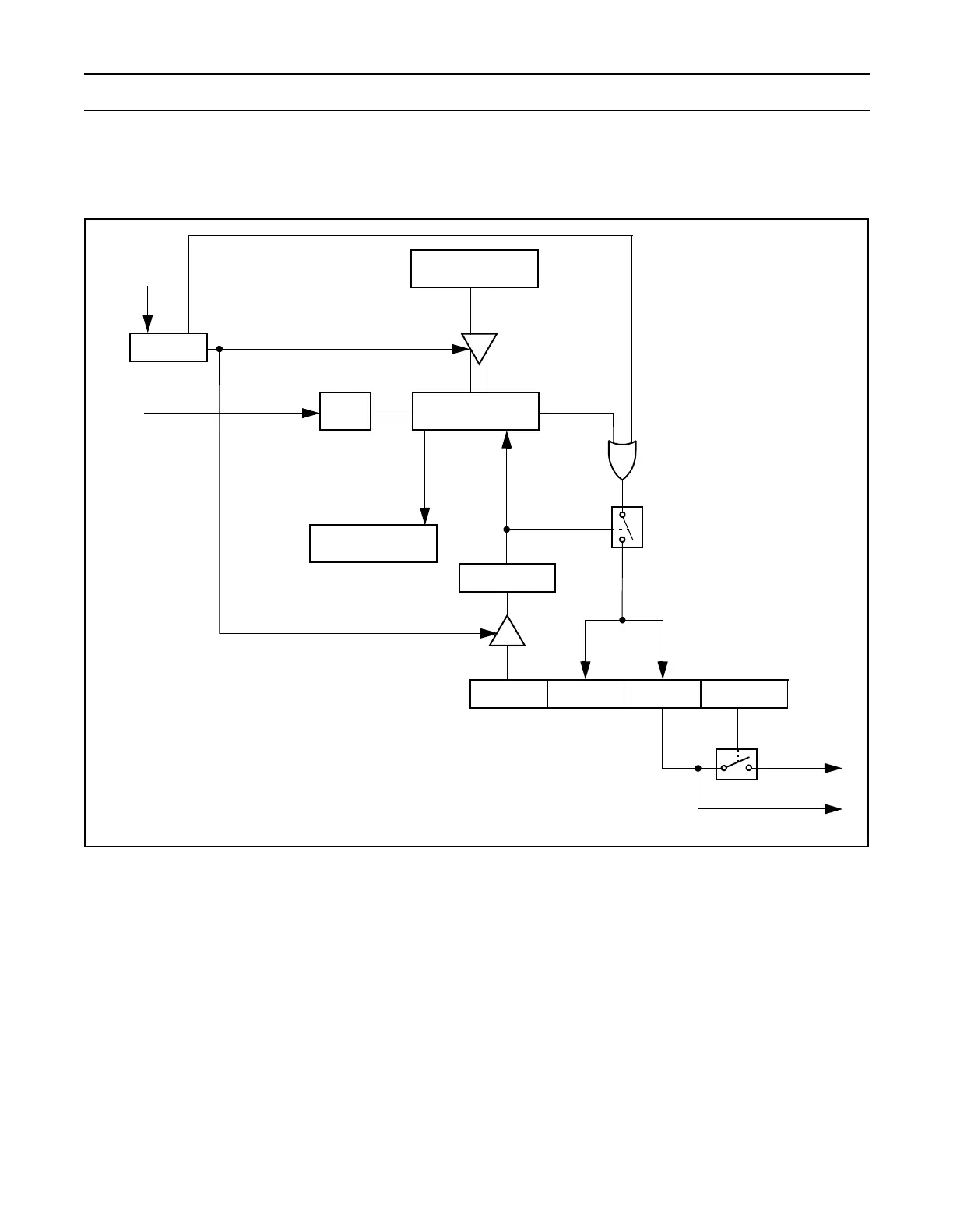
The block diagram of the Watchdog is shown below in the Figure 46.
Figure 46: Watchdog Block Diagram
WDEN
2
SHADOW BIT
WDINT
FEED
SEQUENCE
WDFEED
32-BIT DOWN
COUNTER
WDTC
WDTOF
pclk
RESET
WDMOD
REGISTER
/ 4
INTERRUPT
FEED OK
FEED ERROR
WDRESET
2
CURRENT WD
TIMER COUNT
WDTV
REGISTER
1. Counter is enabled only when the WDEN bit is set
and a valid feed sequence is done.
2. WDEN and WDRESET are sticky bits. Once set
they can’t be cleared until the Watchdog underflows
or an external reset occurs.
ENABLE
COUNT
1
UNDER
FLOW