System Control Block 77 May 03, 2004
Philips Semiconductors Preliminary User Manual
LPC2119/2129/2194/2292/2294ARM-based Microcontroller
The PLL must be set up, enabled, and Lock established before it may be used as a clock source. When switching from the
oscillator clock to the PLL output or vice versa, internal circuitry synchronizes the operation in order to ensure that glitches are
not generated. Hardware does not insure that the PLL is locked before it is connected or automatically disconnect the PLL if lock
is lost during operation. In the event of loss of PLL lock, it is likely that the oscillator clock has become unstable and disconnecting
the PLL will not remedy the situation.
PLL Configuration Register (PLLCFG - 0xE01FC084)
The PLLCFG register contains the PLL multiplier and divider values. Changes to the PLLCFG register do not take effect until a
correct PLL feed sequence has been given (see PLL Feed Register (PLLFEED - 0xE01FC08C) description). Calculations for the
PLL frequency, and multiplier and divider values are found in the PLL Frequency Calculation section.
PLL Status Register (PLLSTAT - 0xE01FC088)
The read-only PLLSTAT register provides the actual PLL parameters that are in effect at the time it is read, as well as the PLL
status. PLLSTAT may disagree with values found in PLLCON and PLLCFG because changes to those registers do not take effect
until a proper PLL feed has occurred (see PLL Feed Register (PLLFEED - 0xE01FC08C) description).
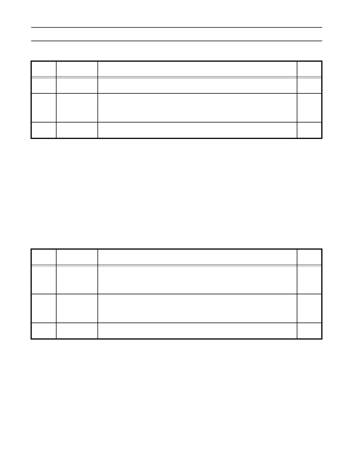
Table 22: PLL Control Register (PLLCON - 0xE01FC080)
PLLCON Function Description
Reset
Value
0 PLLE
PLL Enable. When one, and after a valid PLL feed, this bit will activate the PLL and
allow it to lock to the requested frequency. See PLLSTAT register, Table 24.
0
1 PLLC
PLL Connect. When PLLC and PLLE are both set to one, and after a valid PLL feed,
connects the PLL as the clock source for the LPC2119/2129/2194/2292/2294.
Otherwise, the oscillator clock is used directly by the LPC2119/2129/2194/2292/2294.
See PLLSTAT register, Table 24.
0
7:2 Reserved
Reserved, user software should not write ones to reserved bits. The value read from a
reserved bit is not defined.
NA
Table 23: PLL Configuration Register (PLLCFG - 0xE01FC084)
PLLCFG Function Description
Reset
Value
4:0 MSEL4:0
PLL Multiplier value. Supplies the value "M" in the PLL frequency calculations.
Note: For details on selecting the right value for MSEL4:0 see section "PLL Frequency
Calculation" on page 79.
0
6:5 PSEL1:0
PLL Divider value. Supplies the value "P" in the PLL frequency calculations.
Note: For details on selecting the right value for PSEL1:0 see section "PLL Frequency
Calculation" on page 79.
0
7 Reserved
Reserved, user software should not write ones to reserved bits. The value read from a
reserved bit is not defined.
NA