FL MGUARD RS4000 TX/TX-P
128
PHOENIX CONTACT 105656_en_05
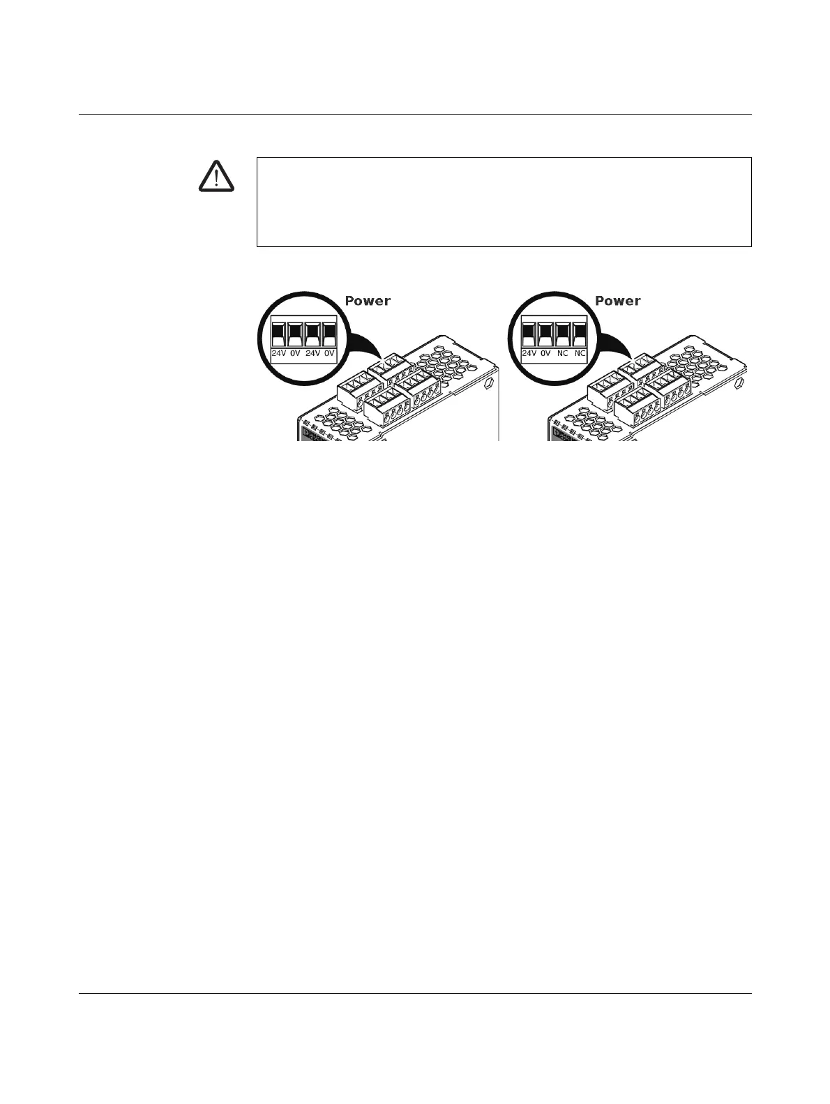
6.4.4 Connecting the supply voltage
The supply voltage is connected via a plug-in screw terminal block, which is located on the
top of the device.
Figure 6-4 Connecting the supply voltage
Instead of the designation 24V/24V the designation US1/US2 is also used.
The device has a redundant supply voltage. If you only connect one supply voltage, you will
get an error message.
• Remove the plug-in screw terminal blocks for the power supply and the service con-
tacts.
• Do not connect the service contacts to an external voltage source.
• Wire the supply voltage lines with the corresponding screw terminal block 24V/24V (re-
sp. US1/US2) of the device. Tighten the screws on the screw terminal blocks with
0.5 ... 0.8 Nm.
• Insert the screw terminal blocks into the intended sockets on the top of the device (see
Figure 6-4).
Status LED P1 lights up green when the supply voltage has been connected properly. On
the device, the status indicator P2 also lights up if there is a redundant supply voltage con-
nection.
The device boots the firmware. Status STAT LED flashes green. The device is ready for op-
eration as soon as the Ethernet socket LEDs light up. Additionally, status LEDs P1/P2 light
up green and the status STAT LED flashes green at heartbeat.
Redundant voltage supply
A redundant supply voltage can be connected. Both inputs are isolated. The load is not dis-
tributed. With a redundant supply, the power supply unit with the higher output voltage sup-
plies the device alone. The supply voltage is electrically isolated from the housing.
If the supply voltage is not redundant, the device indicates the failure of the supply voltage
via the signal contact. This message can be prevented by feeding the supply voltage via
both inputs 24V/24V (resp. US1/US2)) or by installing an appropriate wire jumper between
connections 24V and 24V (resp. US1 and US2).
WARNING: The device is designed for operation at DC voltages of
11 V DC ... 36 V DC/SELV.
Therefore, only SELV circuits with voltage limitations according to
IEC 60950/EN 60950/VDE 0805 may be connected to the supply connections and the
signal contact.
 Loading...