ILC 131 STARTERKIT
22
PHOENIX CONTACT 105724_en_01
4.5 “Bus Structure” window
The “Bus Structure” window is used to display and edit the bus topology of the project.
4.5.1 Icons in the “Bus Structure” window
4.5.1.1 Logical device functions
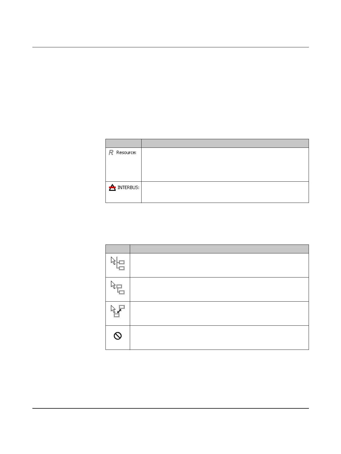
The individual device functions are identified in the “Bus Structure” window with logical
icons. The logical icons in the example bus configuration have the following meaning:
4.5.1.2 Validity of actions
When editing the bus configuration with the mouse, the mouse pointer indicates the validity
of your actions.
Table 4-1 Icons for logical device functions (examples)
Icon Meaning
Controller resource
When creating the project using a template, the controller resource is
inserted below this icon.
When creating the project using the wizard, the controller resource is
inserted below this icon.
INTERBUS master
Below this icon, insert the INTERBUS devices that are directly connected
to the device that this icon refers to (local bus and remote bus).
Table 4-2 Icons when editing the bus configuration
Icon Meaning
Insert at the same level
The device can only be inserted in/moved to the same level as existing
devices.
Insert in the lower level
The device can only be inserted in/moved to a lower level than existing
devices.
Replace
The device under the mouse pointer can be replaced by holding down the
<Ctrl> key and placing the mouse pointer on the existing device.
Not permitted
This icon indicates a mouse pointer position for which actions are not
permitted.



 To Next Page