ILC 131 STARTERKIT
64
PHOENIX CONTACT 105724_en_01
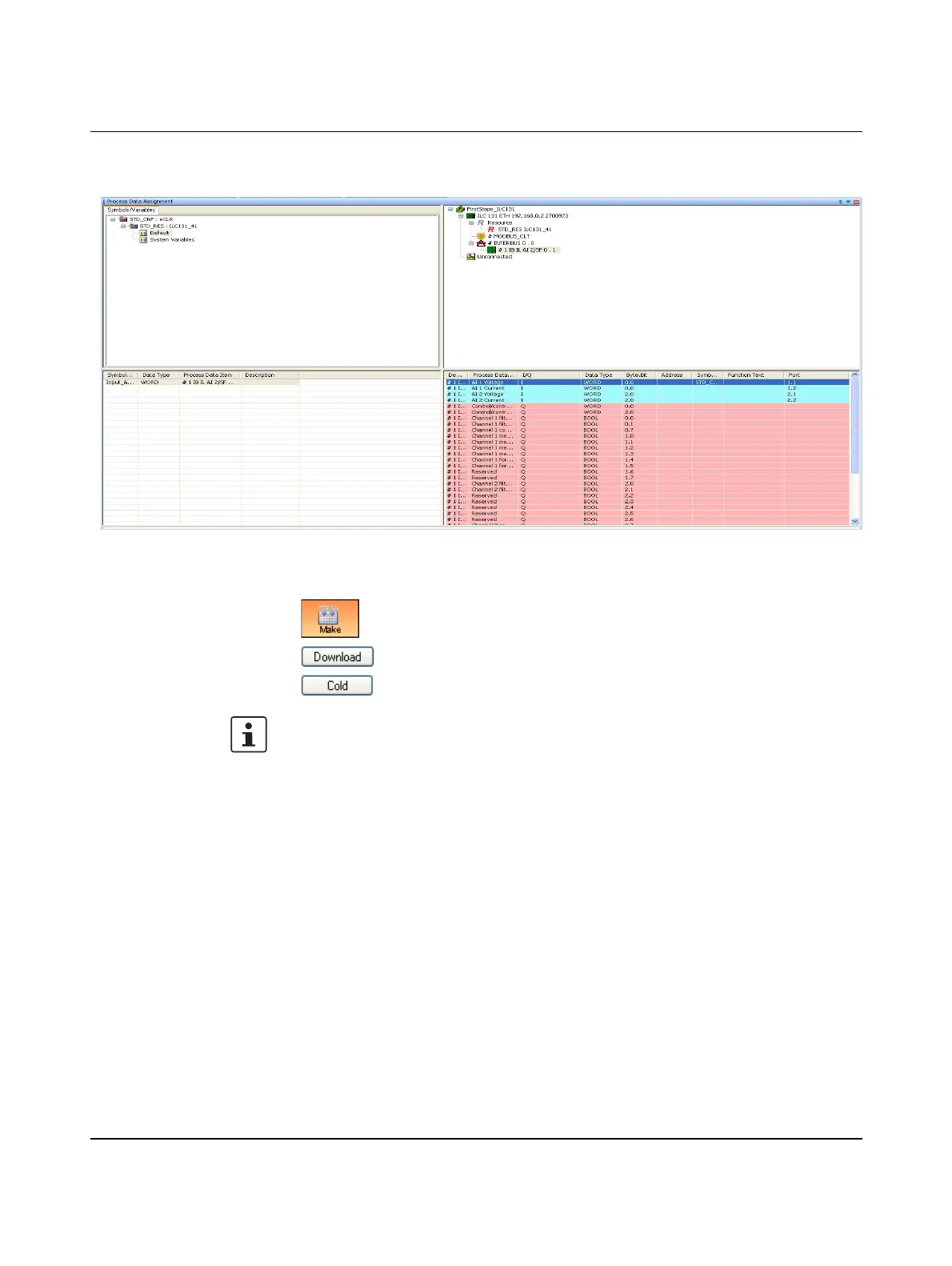
In the bottom left window, the assignment between the variable and process data item is
displayed.
Figure 5-46 Process Data Assignment
Compiling the program,
transmitting it to the
controller, and performing
a cold restart
The ILC 131 ETH has been started up successfully if the green FR LED is on.
Testing the program • Activate switches 0/1 of the switch module or change the potentiometer setting to test
the program.
Switch 0 (ONBOARD_INPUT_BIT0) switches the clock signal (clock) to the output
(ONBOARD_OUTPUT_BIT0). Switch 1 (ONBOARD_INPUT_BIT1) is used to switch over
the clock frequency (timeclock).
If all of the steps described above have been carried out properly, the Q1 LED flashes when
switch 0 is set to ON (I1 LED lights up). With switch 1 set to OFF, the time constant is
0.25 seconds; with switch 1 set to ON, the time constant is 1 second.
In order to view changes to analog value variables (Input_Analog/Output_Analog), you
must switch to debug mode. When debug mode is activated in PC WORX EXPRESS, the
variable status can be viewed online. For additional information about debug mode, please
refer to Section 5.4, “Operation and debug mode – viewing values online”.
Compile the program that has been created.
To test the program, transmit it to the controller.
To activate the project, perform a cold restart for the controller.
For a more detailed description, please refer to “Compiling the program” on page 54.



 To Next Page