ILC 131 STARTERKIT
46
PHOENIX CONTACT 105724_en_01
5.2.2 Program description
This section describes program steps, which can be used to set up the entire
“FirstSteps_ILC131.mwe” example project. These program steps are used in Section 5.3,
“Creating the program” to set up the entire “FirstSteps_ILC131.mwe” example project
step-by-step.
1 Direct linking of a controller input with a controller output using onboard variables
– Creating variables (user variables/system variables)
– Linking variables
2 Use of function blocks from the function block library
– Selecting a function block from the library and inserting it in the worksheet
– Wiring/connecting the inputs and outputs of function blocks
– Linking onboard variables using a function block
3 Connecting function blocks using the example of clock generation
– Fixed clock
– Variable clock
4 Direct linking of two analog value variables/process data assignment/complete
program
– Creating analog value variables
– Process data assignment of a device input to an analog value variable
– Designating variables for transfer to visualization tools
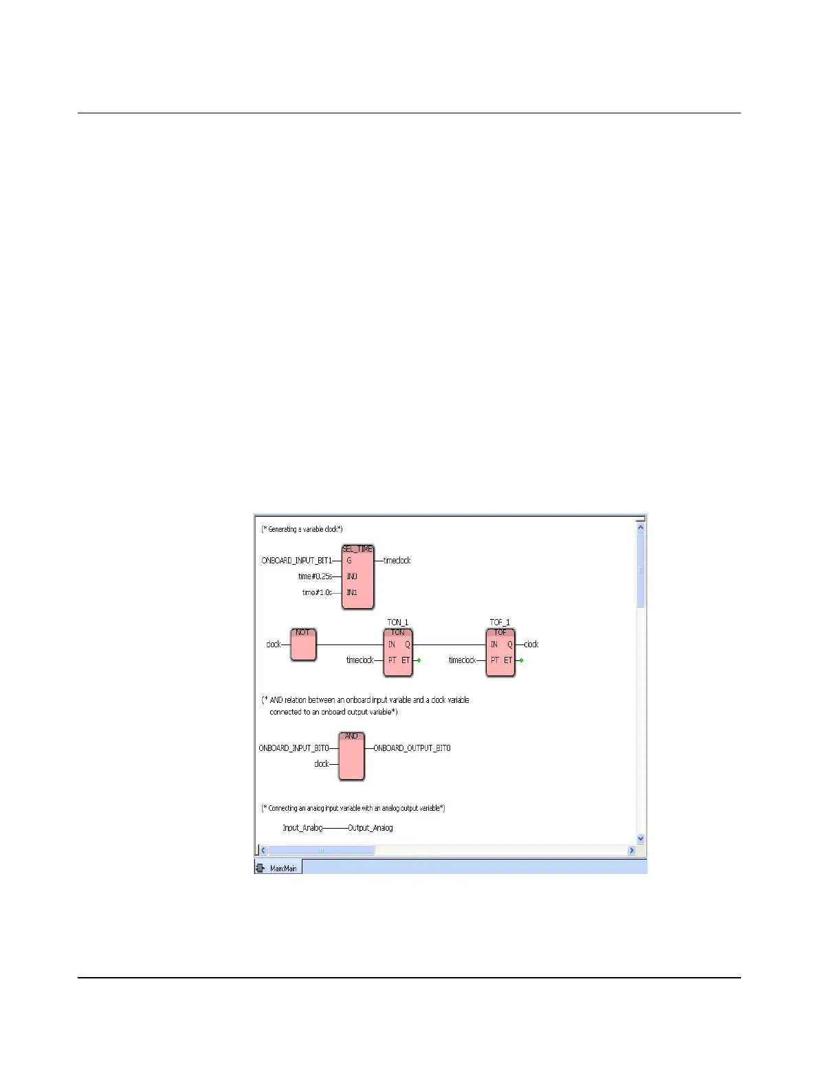
“FirstSteps_ILC131.mwe”
program code
Figure 5-20 “FirstSteps_ILC131.mwe” complete program



 To Next Page