PHOTONIS | 22
NVT 200-LC-0103
Revision: D
Page 22 of 43
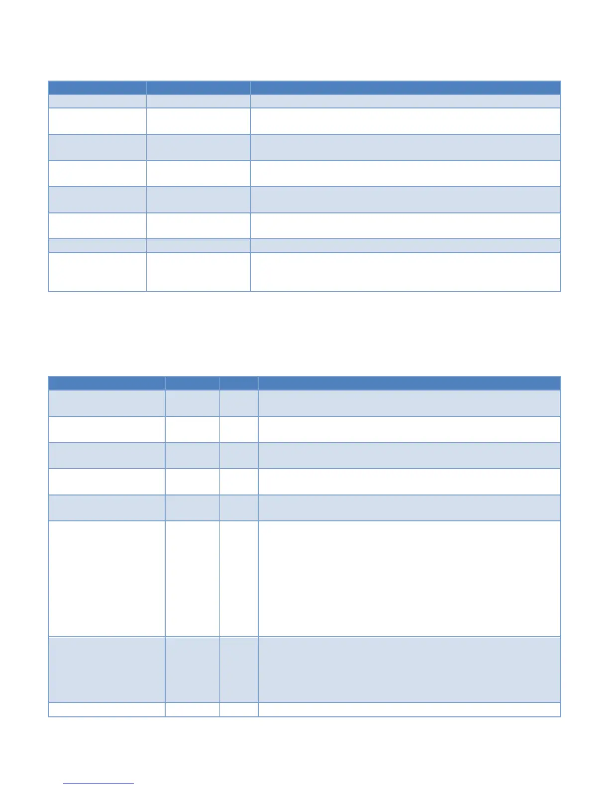
Sets the line noise filter to use 16 columns
Sets the video black offset when the line noise filter is
enabled
Clears the sensor active signal to the CMOS image sensor
Sets the sensor active signal to the CMOS image sensor
Displays camera sensor register default table data in console
(store in camera)
Displays current sensor register settings read from sensor on
the console
Reads camera sensor register address xx and displays value
on the console
Writes camera sensor register address xx with value dd
Saves current sensor register settings as power on default
(the gain and exposure settings will be ignored and the
values entered in under the agc setup table will be used)
A list of all possible registers for the “cs wr” and “cs rd” is given in Table 16.
Table 16 CMOS Sensor Registers
Disable/Enable continuous grabbing of images;
external SENSOR_ACTIVE pulses are ignored
Use 2 or 4 output channels, resulting in 60fps or 100
fps operation
The start address of the readout window.
Valid range for this register is 0 to 1044-SIZE_Y.
The number of rows in the readout window.
Valid range for this register is 1 to 1044
The number of slopes is 1, 2 or 3.
‘0’ is an invalid setting for this register.
The number of slots light integrates on the pixels for the first
slope of the response curve.
The default value yields the maximum integration time
available while maintaining the desired maximum frame
rates of 60fps and 100fps. A longer integration time will
decrease the frame rate.
‘0’ is an invalid setting for this register.
The number of slots light integrates on the pixels for the
second slope of the response curve.
By default, the second slope is not used, so the default
value is 0.
The number of slots light integrates on the pixels for the
 Loading...