Check the presence of fixed voltage between the
grey/black cable of the remote control base and
earth. If there is none check the continuity of the
grey/black cable between the fuse box (No. 4 10
A) and the remote control base.
N.B.
CONTINUITY TESTS MUST BE CARRIED OUT WITH THE
COMPONENTS DISCONNECTED. (SOLENOIDS, CON-
TROL UNIT, FUSES ETC.).
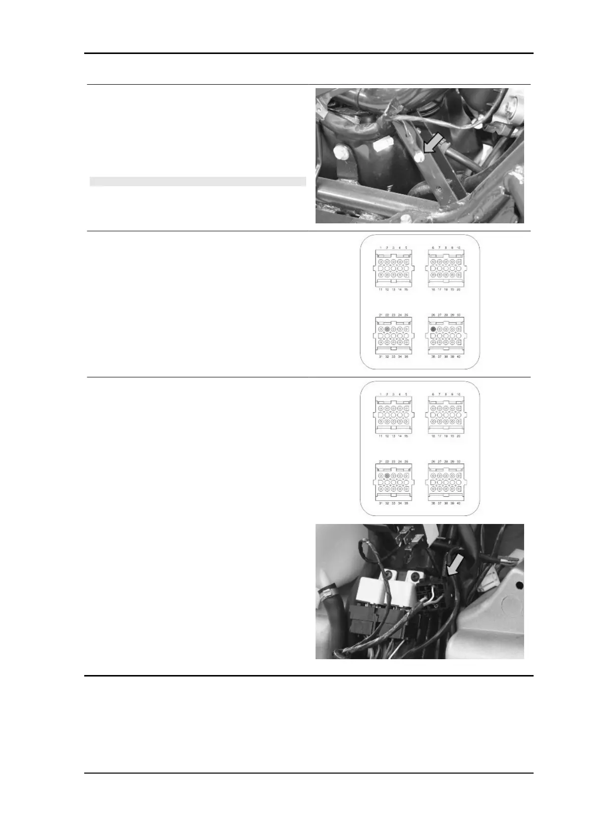
Check there is voltage between pins 22 and 26 of
the interface wiring for around two seconds when
switching to «ON».
Check the resistance of the primary coil between
pin 22 of the interface wiring and the green black
cable of the injection load solenoid base with the
control unit disconnected and the solenoid discon-
nected.
Resistance of the primary = 0.5 ± 8% Ohm
Beverly Tourer 300 i.e. Injection
INJEC - 201