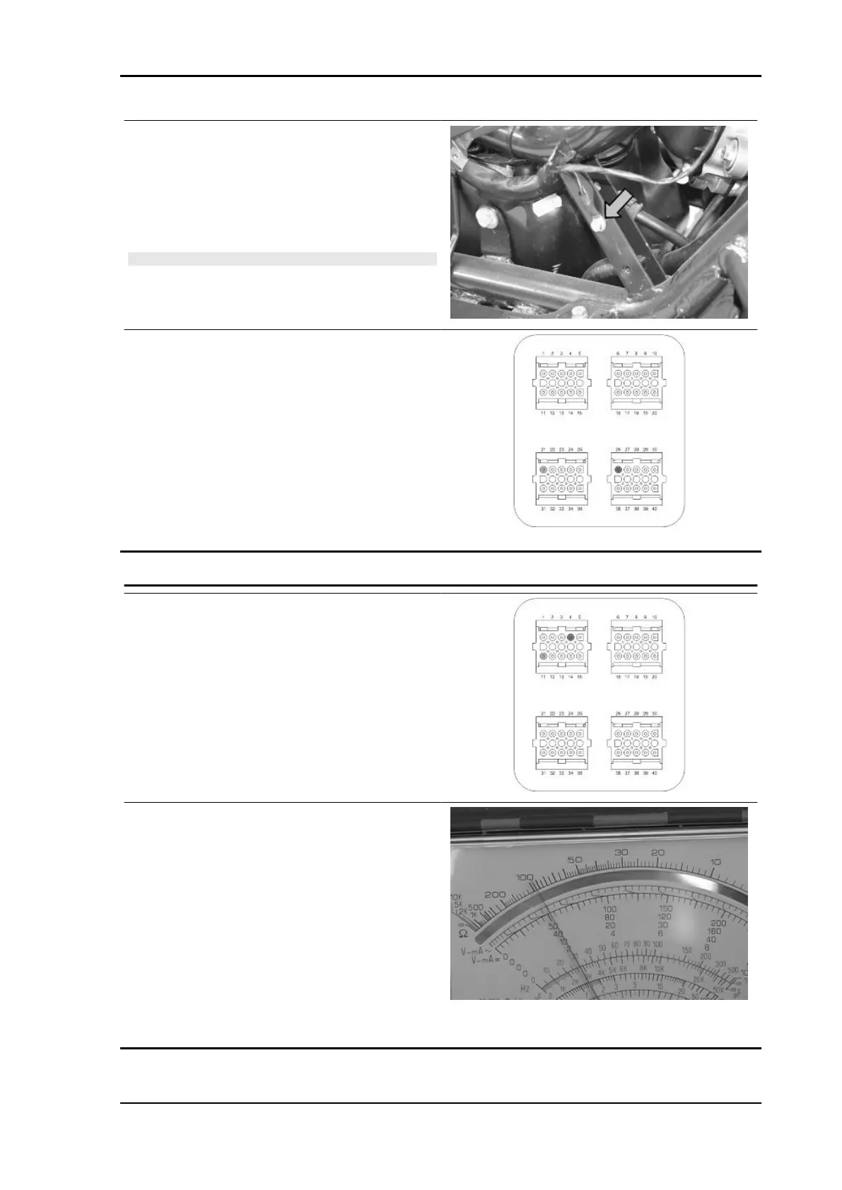
Check the presence of fixed voltage between the
grey/black cable of the remote control base and
earth. If there is none check the continuity of the
grey/black cable between the fuse box (No. 4 10
A) and the remote control base.
N.B.
CONTINUITY TESTS MUST BE CARRIED OUT WITH THE
COMPONENTS DISCONNECTED. (SOLENOIDS, CON-
TROL UNIT, FUSES ETC.).
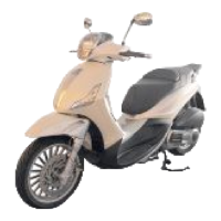
Check there is voltage between pins 21 and 26 of
the interface wiring, for around two seconds, when
switching to «ON».
SIGNAL CONTROL
Install the electronic control unit interface wiring.
Start the engine and warm up until the electric fan
switches on.
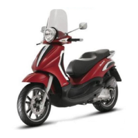
Use an analogue multimeter with a direct voltage
scale measuring down to 2 V.
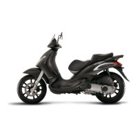
Place the tips of the multimeter between pins 4 (-)
and 11 (+)
With the engine running at idle speed, check that
the voltage oscillates between 0V and 1V
With the throttle valve completely open, the volt-
age is approx. 1V.
During the closing phase, the voltage is approx.
0V.
If the voltage remains constant, the sensor may be
damaged. Remove the sensor and check that
there are no oil or carbon deposits inside it..
Beverly Tourer 300 i.e. Injection
INJEC - 209










 To Next Page