The body and the reaction plate body work inte-
grally and can move axially with respect of the
fixed plate that is integral to the strut.
The pistons, forced by pressure to push the pad to
the disk, cause the reaction plate to push in turn
the other pad towards the disc.
The brake pad lock spring
1. Pad fixing screws
2. Reaction plate fixing screws
3. Reaction plate
4. Fixed plate
5. Floating body
6. Piston
7. Piston sealing rings
8. Guide protection rubbers
9. Brake pad check spring
10. Pads
CAUTION
ALL THE SEALS AND GASKETS MUST BE REPLACED EV-
ERY TIME THE CALLIPER IS SERVICED.
Locking torques (N*m)
Brake fluid tube-calliper fitting 20 ÷ 25 Pad fas-
tening pin 19.6 ÷ 24.5
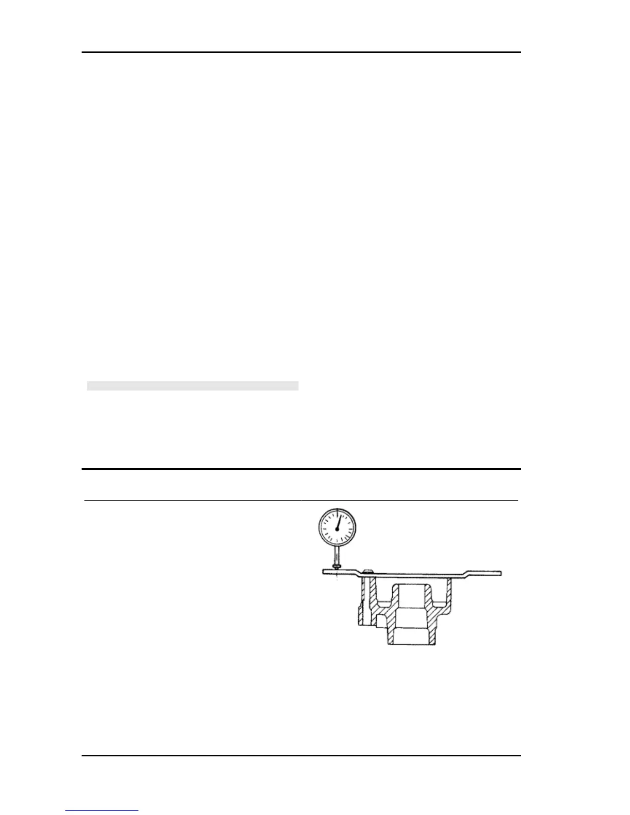
Removal
Remove the wheel and check that the axial devi-
ation of the braking surface is within in the recom-
mended values:
- If this is not the case, replace the disc and repeat
the test.
If the problem persists, check and replace the
wheel hub if necessary.
Front/rear disc replacement
1) disassemble the front/rear wheel;
2) loosen the two fixing screws and remove the
disc.
When refitting, position the disc correctly, respect-
ing the direction of rotation, and apply medium
threadlock.
Braking system X9 Evolution 125
BRAK SYS - 180