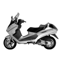
Checking the bell working surface eccentricity
- Install the bell on a driven pulley shaft using 2
bearings (inside diameter: 15 and 17 mm).
- Lock with the original spacer and nut.
- Place the bell/shaft unit on the support to check
the crankshaft alignment.
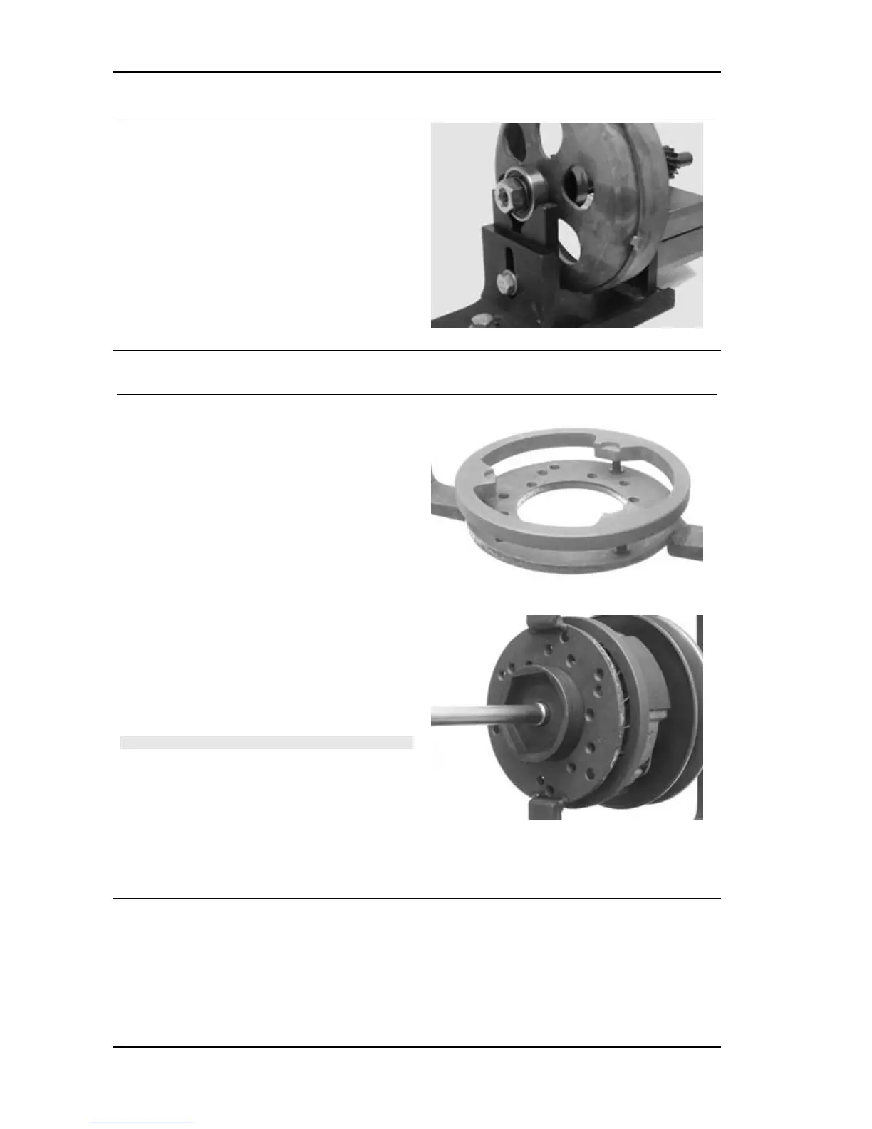
Removing the clutch
Removing the clutch
Fit the driven pulley spring compressor specific
tool with medium length pins screwed in position
F from the tool internal side.
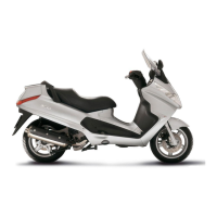
- Insert the adapter ring 8 in the pins.
- Assemble the driven pulley unit on the tool intro-
ducing the rivets heads in the adapter ring.
- Make sure that the clutch is perfectly inserted into
the adapter ring before proceeding to loosen/tight-
en the clutch nut.
- Use the special 46x55 wrench component n°9 to
remove the nut fixing the clutch in place.
- Separate the driven pulley components (Clutch,
fan and spring with plastic fitting).
CAUTION
THE TOOL MUST BE FIRMLY FIXED IN THE CLAMP AND
THE CENTRAL SCREW MUST BE BROUGHT INTO CON-
TACT WITH THE TOOL. EXCESSIVE TORQUE CAN CAUSE
THE SPECIFIC TOOL TO BUCKLE.
Specific tooling
020444Y009 wrench 46 x 55
020444Y010 adapter ring
Engine X9 Evolution 125
ENG - 92