PicoQuant GmbH HydraHarp 400 Software V. 3.0.0.1
The picosecond diode laser (PDL 800–B) is triggered by its internal oscillator (settable at 2.5, 5, 10, 20 and 40
MHz). The driver unit is physically separate from the actual laser head, which is attached via a flexible cable.
This permits to place the small laser head conveniently anywhere in the optical setup. The light pulses of
typically <70 ps FWHM, are directed toward the sample cuvette via appropriate optics. A neutral density filter
can be used to attenuate the light levels if necessary. Upon excitation, the fluorescent sample will emit light at a
longer wavelength than that of the excitation light. The fluorescence light is filtered out from scattered excitation
light by means of an optical cutoff filter (other configurations may utilize a monochromator here). Then it is
directed to the photon detector, again possibly via some appropriate collection optics, e.g. a microscope
objective or a lens.
As a photon detector the H5783 PMT from Hamamatsu is very convenient. It only needs a 12 V supply and
permits an instrument response width of <250 ps, allowing lifetime measurements even much shorter than this
via deconvolution. If a higher time resolution is required, the detector of choice is an MCP–PMT. The electrical
signal obtained from the detector (small negative pulses of typically −10 to −50 mV) is fed to the TCSPC
electronics via a preamplifier (e.g. PAM 105 from PicoQuant). This gives pulses of −100 to −500 mV. Cabling is
double shielded 50 Ω coax cable. If the detector is a SPAD module with TTL output (SPCM–AQR from
Excelitas, formerly Perkin Elmer) then an inverter / attenuator (SIA 400) must be inserted. Modern SPAD
devices like the PDM series from MPD directly provide negative timing signals.
The PDL 800–B laser driver readily provides the electric sync signal needed for the photon arrival time
measurement. This signal (a narrow negative pulse) is also fed to the TCSPC electronics via a high quality
50 Ω coax cable. When using the HydraHarp 400 in combination with the PDL 800–B, the sync pulse adapter
LTT 100 (brass cube with SMA connectors) or a 10 dB attenuator should be inserted directly at the sync output
of the laser driver. This reduces crosstalk into the relatively weak detector signals. If the laser does not provide
an electrical sync signal (e.g. Ti:Sa lasers), a sync detector (photo diode) such as the TDA 200 must be used.
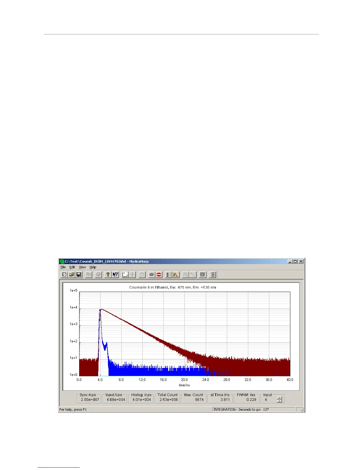
The following figure shows TCSPC histograms obtained with this setup. Excitation source was a PDL 800–B
with a 470 nm laser head running at 20 MHz repetition rate. The narrower (blue) curve represents the system
IRF, here dominated by the detector (PMT). The other curve (dark red) is the fluorescence decay from a
solution of Coumarin 6 in ethanol, a fluorescent dye with fairly short fluorescence lifetime (~2.5 ns). The count
rate was adjusted to <1% of the laser rate to prevent pile–up. The plot in logarithmic scale shows the perfect
exponential nature of the decay curve, as one would expect it. Note that this is obtained even without a
deconvolution of the IRF.
Page 13